• Please review our updated Terms and Rules here

Macintosh Color classic headphone/speaker out not working correctly

VERAULT

Veteran Member
Joined
Jan 30, 2012
Messages
8,434
Location
Connecticut, USA
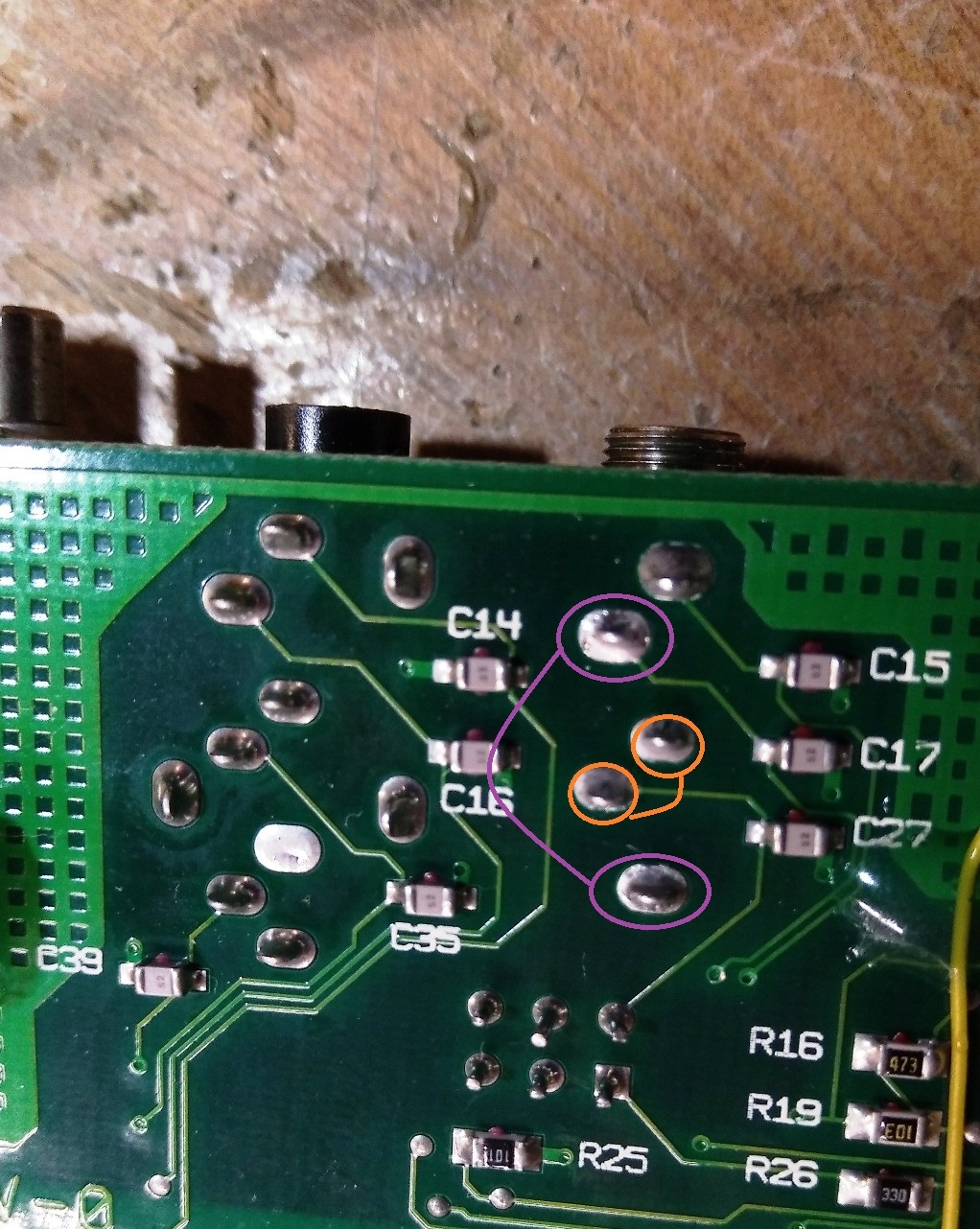
So I had to replace a bad Dfac2 chip on my color classic board to get any audio. When I plug a speaker or headphone set into the audio out I am expecting to get stereo audio out and the internal speaker to cut out.. But the internal speaker keeps playing audio and the audio out only plays audio via the left channel (left earphone).


This does not seem like normal behavior. My LC575 which is of a similar vintage gives me stereo out via the headphones (both headphones give sound) and the internal speaker cuts out when plugged in. So the fact theat the MAC color classic isnt doing any of that seems something is way off.

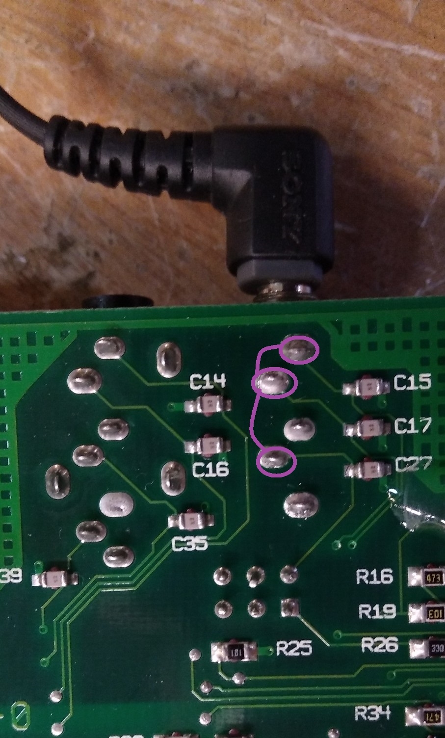
I think the next step is to replace the audio jack. But before I go to that length. Can someone with a Macintosh Color classic please test a pair of head phones on the audio out jack in back and see if they get audio for one, and if the internal speaker still plays audio or cuts out?

Thanks
 
Color Classics had stereo output jacks, but comes out only mono if I recall correctly. It should cut off the machine when headphones are inserted. I clean the jack with some wd-40 or dexoit and see what ya get. Worked this way on my LC 475, so I assume it be the same for a color classic as they are interchangeable.
 
Cleaned it several times, no change. Checked solder points of audio jack and all work. IT is not operating correctly.
 
Have you checked the SMT caps leading to the headphone jack? If one is shorted could cause symptoms you are describing. Might not be the jack. Knowing this era Mac, and how these caps love to leak, I look for traces of Cap poop. I'd solder a wire to each pin of the jack and use a crap speaker to test both sides to rule out the jack. Dollar store headphones work in a pinch if you have nothing else to test with.
 
No need to, the system has been recapped. And I have plenty of verified working headphones. Definitely the system.
 
Ok maybe I found something.so I found that pins 37 and 38 on U5 (DFAC2) are shorted (have continuity). Using magnification I can find no solder causing the short.Going by the schematic page 11, pins 37 and 38 goto the headphone jack.So the first photo shows what pins on the jack have continuity when no headphone is inserted.
IMG_20220518_112917.jpg


And when the headphone jack is inserted the continuity on the jack changes to this:
IMG_20220518_113653.jpg
 
The Color Classic has a stupid design fault where it has either a two or three way split isolated ground plane on the logic board that needs to be connected for sound to work properly. How did Apple do this? They used the RF shield in the chassis touching the ground plane pads to connect them all together.

Adrian has a video from early in 2021 about it:

If the RF shield is not connected, or has a bad connection to the board, the sound won't work properly and you'll be chasing ghosts.
 
Thanks Gigabite. I thought about this as well since I remember that video from the past. The board has all the ground posts. the system DOES NOT have the main RF cage. judging by the chassis when I got it, it had rusted away. Regardless, this board has only one ground plane as all points which should touch the RF shield have continuity to one another. That said I used alligator clips to connect the ground plane to the ground of the Analog/CRT board. It made no difference in sound. So I am no sure what I am doing wrong as that should provide the ground if it was missing.

But I dont think its the same as in the video as the system has sound working fine out the internal speaker. Its the speaker output which isnt working properly.
 
Last edited:
Maybe solder a wire to each ground where the RF shield was? I mean correct me if i'm wrong if not understanding the situation, but Verault you have a machine that is acting same way as the machines without the RF shields installed, Wouldn't it just make sense at this point to solder a ground wire to every point the RF shields were soldered to? I would say use ground clips but that be at least 12 ground clips... Perhaps there is a floating ground in there somewhere, and would be easier just to connect them all back to ground, then spend the time tracing it out? Cant see it take more then 5 minutes to rule it out. I dunno its what I would do next. 🤷
 
Last edited:
Unline in the video my ground plane is no broken into sections. And I do get audio without the RF shield. I am suspecting the problem is the DFAC2 IC.
 
Back
Top