• Please review our updated Terms and Rules here

MDA TTL to composite video

syzygy

Experienced Member
Joined
Apr 22, 2023
Messages
392
Location
North East USA
I have interest in this circuit to use a composite video input into a "modern LCD monitor" from the TTL video output from a PC MGA and similar clone boards. Has anyone here actually built this and can render an opinion?

Circuit is from Jozef Bogin - http://boginjr.com/electronics/rad/rgbi/

SCHEMATIC

(I am interested only in the MDA side)
 
Unless you have a very unusual "modern" LCD monitor that can reach down to 18.432Khz horizontal/50Hz vertical, that circuit isn't going to work. It was fairly easy to "tweak" CRT monitors into that range, but probably not LCDs.

A scan converter would be the ticket, I think.
 
Better replace the MDA card by Hercules or CGA and then the conversion to some NEC TFT Multisyncs, like 1990fxi, 1970nxp, etc. should be possible.
 
Better replace the MDA card by Hercules or CGA and then the conversion to some NEC TFT Multisyncs, like 1990fxi, 1970nxp, etc. should be possible.
My 5150 has a Hercules clone card that feeds an MCE2VGA that in turn feeds a generic flat screen VGA monitor.

Works great.
 
Jozef Bogin said:
Of course, even here, the display device (or TV) must be able to sync up to the video signal. With a mono CGA, it’s enough for the TV just to support NTSC. (...) But with an MDA or Hercules, 99.9 % of TVs won’t sync to those frequencies, resulting in a corrupted or a blank picture.

Sums it up quite nicely. If you don't have a CRT to tinker with, your best bet is a converter
 
Thanks all for the discussion. I still might try that circuit, but probably for CGA and not MDA because the card that I had in mind is probably not an MDA, as far as I can tell - should have looked closer. I will just need to be able to see it boot - if it does.
 
If you’re happy with monochrome output from your CGA card (which is all you’re going to get with that circuit) I would actually suggest a modification: as it’s written it only uses the “Green” and “Intensity“ lines. That’ll work okay with white (and green/yellow/cyan, sort of) text but any red/blue/purple text isn’t going to show up *at all*. Instead I’d suggest using four resistors on all of RGBI to give you a full 16 shades of grey.

For suggested values/ratios of these resistors look at the schematics for a CGA card upstream of the composite out. (Which I assume your card doesn’t have.) The Tandy 1000 service manuals have a nice clear layout for this, the resistors are hanging in parallel off the same lines going to the digital port. Mix in the sync as that schematic you’re working from shows.

(* The exact ratio of the resistors you use doesn’t really matter that much, I’d just suggest using the same weighting as a real CGA so anything running on it won’t look “off” compared to the same thing running on an IBM with a composite driven monitor, like a 5155.)
 
As a matter of fact, here's above circuit on a Hercules clone, displayed on a CRT video doorbell.
Forgive me for the slanted top, I have not degaussed the CRT yet. Or perhaps I might add some magnets to straighten it up :)
The reason the first and last columns are not visible fully is due to a short flyback pulse here, not the circuit itself. The second picture (the one with Pipboy) is when switched to CGA - the machine had no composite out.
 

Attachments

  • Clipboard02.jpg
    Clipboard02.jpg
    193.5 KB · Views: 36
  • CGA.jpg
    CGA.jpg
    128 KB · Views: 34
Last edited:
If you’re happy with monochrome output from your CGA card (which is all you’re going to get with that circuit) I would actually suggest a modification: as it’s written it only uses the “Green” and “Intensity“ lines. That’ll work okay with white (and green/yellow/cyan, sort of) text but any red/blue/purple text isn’t going to show up *at all*. Instead I’d suggest using four resistors on all of RGBI to give you a full 16 shades of grey.

For suggested values/ratios of these resistors look at the schematics for a CGA card upstream of the composite out. (Which I assume your card doesn’t have.) The Tandy 1000 service manuals have a nice clear layout for this, the resistors are hanging in parallel off the same lines going to the digital port. Mix in the sync as that schematic you’re working from shows.

(* The exact ratio of the resistors you use doesn’t really matter that much, I’d just suggest using the same weighting as a real CGA so anything running on it won’t look “off” compared to the same thing running on an IBM with a composite driven monitor, like a 5155.)

Thanks. The situation is that I need any kind of visible output using a 2008 Venturer PLV76198 LCD monitor, which I have on hand, so that I can see if it will boot. A keyboard is on the way (assuming that it has an XT/AT switch, which it looked like it does.

I have no docs on the board and posted it here - there is a mysterious 2 pin connector that *could* be a composite out or it could be something else - for crying out loud, the board has a Light Pen port (labeled L Pen)...I'm assuming it is a light pen - I haven't seen one of those in at least 30 years!

I'm flying blind but that is a very simple circuit and I should have a couple of connectors around here somewhere.
 
As a matter of fact, here's above circuit on a Hercules clone, displayed on a CRT video doorbell.

Bah. I ordered a couple of those video doorbell screens off AliExpress when they were all over the place, but neither one seemed to work right? I wired them up according to the schematics and I could get a gray screen with the brightness cranked up, but no composite input I tried gave me a raster. Bad luck I guess.
 
Yeah, there's a probability that you got a lemon. IIRC mine required two new trimpots and 12V DC to start., with some tinkering on a test card to get somewhat reasonable images. Always fun going around the tiny flyback transformer with a screwdriver.
 
Eudimorphodon said:
but any red/blue/purple text isn’t going to show up *at all*

You have a point there, but it's not that bad, actually. Here's Grand Prix F1 from DSI (running GPCGA.EXE with the ugly cyan/purple palette), DOS EDIT which has a solid blue background turned black, but still usable.. Also Windows 1.01 there. But yes, you want to combine all RGB lines to get shades of gray if wished.
 

Attachments

  • GPCGA.jpg
    GPCGA.jpg
    213.3 KB · Views: 18
  • EDIT.jpg
    EDIT.jpg
    80 KB · Views: 18
Last edited:
Yeah, there's a probability that you got a lemon. IIRC mine required two new trimpots and 12V DC to start., with some tinkering on a test card to get somewhat reasonable images. Always fun going around the tiny flyback transformer with a screwdriver.

If you're ever in the mood to make a short post about the tweaking you did I'd probably be up for taking another crack at getting mine to run. I feel like the issue with them was minor, it looked like the raster was free-running, I'd love to be able to hit it in right place to get it working. Knowing they're capable of scanning up to MDA frequencies is actually a BFD; I have an ATI Small Wonder video card I've been wanting to play with and I don't have an MDA monitor to pair with it.
 
Eudimorphodon said:
it looked like the raster was free-running

With video signal in, means that you're getting garbage on screen, but it's not completely blank, right?
Yes, the horizontal sweep oscillator is free running here. Adjust its frequency, by slowly tuning RV5 "H.HOLD" until you get something intelligible on the screen. If it does not seem to lock in, or you get a "train window" effect with the picture moving sideways, also adjust RV7 "H.SIZE" while adjusting RV5. If you now get a picture, but it is jumping up and down, adjust the vertical sync with RV2 "V.HOLD". If not, check your video input source, supply (12 volts filtered, try a battery).
Afterwards, tune the linearity (tilt - RV6, vertical shift and size - RV8, RV9, horizontal size RV7, flyback focus VR4, flyback screen/sub brightness RV1, RV10), using a test card pattern. Reduce screen/sub brightness if you start seeing vertical retrace.
Tuned for a compromise, you should be able to get an image like this.
 

Attachments

  • testcard.jpg
    testcard.jpg
    172.4 KB · Views: 9
oh and make sure your contrast trimpots are supplied., and they are cranked up. This revision had a pinheader for the panel with brightness and contrast adjusted there.
With the sweep frequency trimpot (RV5) you should be able to hear the flyback whine in one of the extremes, as it goes down to circa 13 kilohertz. With good ears that is :)
Should there be no image still, check the pinheader connection of the deflection coils.
 

Attachments

  • Clipboard01.jpg
    Clipboard01.jpg
    129.1 KB · Views: 4
Unless you have a very unusual "modern" LCD monitor that can reach down to 18.432Khz horizontal/50Hz vertical, that circuit isn't going to work. It was fairly easy to "tweak" CRT monitors into that range, but probably not LCDs.

A scan converter would be the ticket, I think.
Since I started this thread, I wanted to tell folks where it is at (and I have no complaints about thread drift).

The board is a CGA not MDA as I originally thought, and I think I mentioned that.

I slopped together the CGA portion of the circuit. I had most of the components (used 914s instead of 4148s, but so what?), but I only had 10K pots and I used them.
SWAN Vid 20230626_090614.jpg

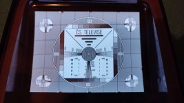
Using the 2008 Venturer PLV76198 LCD monitor that I mentioned, did NOT work. Despite burning incense and chanting (that is, checking and rechecking a simple circuit, cussing a lot and essentially banging my head). Seemed like for a moment or two, I might have seen a whisper of something on the screen, but only for an instant and it could have been a hallucination.

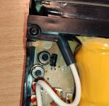
The mysterious 2-pin connector on the board that I mentioned had essentially no voltage on it and that remained constant). The equally mysterious pin 7 on the CGA output DID have ~1 volt. Thinking it may have been composite out, I tested that with the same non-result. Consistent with accepting "you can't get there from here", I let it sit for a while.

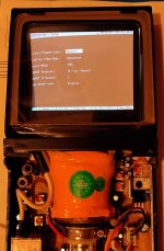
Then I remembered that I had another monitor that I use for my Jetson Nano. I bought this new for $49.99 in April of 2019. RCA RT1970 - has HDMI and a host of other I/O - works pretty well with the Jetson. For S&G, I look through the manual and see this:

rca1.jpg
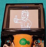
Hmmmm. So that is what led me to slop that circuit and:
swan 20230620_200118.jpg


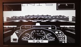
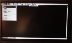
WooFreakinHoo! Now it's off to find whatever I kept as 5.25 PC floppies. I don't even find a full version of any DOS, just bits and pieces of old projects and zips (and arcs) of Turbo C stuff. Undaunted, I play around looking at old programs that actually run, like this one, which was a poker simulation that I had a lot of fun writing many years ago.

swan 20230620_201013.jpg

After a day or so of "oh yeah, I remember that", I get back to business and start trying to resurrect the 225. Spinrite (the old version I still had on floppy and newer versions that I finagled onto floppy wanted no part of it). Checkit led me to believe that the XTGEN controller may be ok, but some (not all) of the surface, is toast.

swan hd test 20230626_085512.jpg

Next stop is LL format land. With a short stop at 3.5" floppy land.

Why did I want to do all this stuff again? :)
 
If you’re happy with monochrome output from your CGA card (which is all you’re going to get with that circuit) I would actually suggest a modification: as it’s written it only uses the “Green” and “Intensity“ lines. That’ll work okay with white (and green/yellow/cyan, sort of) text but any red/blue/purple text isn’t going to show up *at all*. Instead I’d suggest using four resistors on all of RGBI to give you a full 16 shades of grey.

For suggested values/ratios of these resistors look at the schematics for a CGA card upstream of the composite out. (Which I assume your card doesn’t have.) The Tandy 1000 service manuals have a nice clear layout for this, the resistors are hanging in parallel off the same lines going to the digital port. Mix in the sync as that schematic you’re working from shows.

(* The exact ratio of the resistors you use doesn’t really matter that much, I’d just suggest using the same weighting as a real CGA so anything running on it won’t look “off” compared to the same thing running on an IBM with a composite driven monitor, like a 5155.)
Replying again to your post as I am making some progress on the project. I am looking into what you have said and I get and now (literally) see your point.

I have been torn between building something or buying something like this or others that are now hard to find. I am learning that devices like this do not offer a simply "plug and go" solution - for a CGA like mine, you need additional circuitry, as I understand things.

What is striking to me, is the possibility of using a Pi Pico to convert CGA digital to legitimate VGA analog. I am impressed with the VGA capability - see here, for example. I got a pico pretty early on and went through the SDK installation on Win and the encumbrance of using it that way, but it was tolerable. Eventually, I went to an Arduino-IDE varient - and say what you want (real men don't use Arduinos :) ) , but that IDE is just simple. If I keep learning maybe I will go back to the SDK or see what I can play with using the other ways - don't know but wondered if you had any thought on using a Pi Pico to convert digital CGA to analog VGA.
 
I have been torn between building something or buying something like this or others that are now hard to find. I am learning that devices like this do not offer a simply "plug and go" solution - for a CGA like mine, you need additional circuitry, as I understand things.

Yes, you do need a little additional stuff in front of one of these things for them to really work, but it's not a lot. Long story short you need a specialized DAC (digital to analog converter) to convert the CGA RGBI signals to 15khz Analog RGB. It's very misleading that the companies selling cheap scaler boards like the GBS8200 advertise them as "CGA"; apparently in the world of analog video game scalers "CGA" has become a synonym for "TV frequency RGB", and it's wrong because:

A: CGA is digital, not analog
B: CGA has a fourth signal line, "Intensity", that globally affects how the other three lines should be interpreted, and
C: Arcade RGB is usually composite sync, not separate Hsync/Vsync. Depending on the scaler board this needs to be fixed in the converter too.

You can buy off the shelf a dingus to accomplish this conversion for you, and there are plenty of DIY schematics to do it, so it's not a huge deal, but it's still a little aggravating that this confusion exists.


What is striking to me, is the possibility of using a Pi Pico to convert CGA digital to legitimate VGA analog. I am impressed with the VGA capability - see here, for example. I got a pico pretty early on and went through the SDK installation on Win and the encumbrance of using it that way, but it was tolerable. Eventually, I went to an Arduino-IDE varient - and say what you want (real men don't use Arduinos :) ) , but that IDE is just simple. If I keep learning maybe I will go back to the SDK or see what I can play with using the other ways - don't know but wondered if you had any thought on using a Pi Pico to convert digital CGA to analog VGA.

I have a couple Pi Picos I bought to play with months ago that I haven't found time for, but coincidentally enough I've been thinking about seeing about trying to tinker together this exact thing. I mean, on one hand the Pi Zero-based RGBtoHDMI already exists, but it does require an external CPLD and it *feels like* this could be exactly the sort of thing the Pico's little GPIO acceleration functions *might* be able to handle? Maybe? That's just a thing I'm not positive about. CGA's pixel clock is around 14.3mhz, so to capture CGA pixels accurately you need to snapshot 4 bit samples either perfectly synchronously at around that rate or asynchronously at around twice that fast. Someone who's actually worked with the Pico would probably be better able to tell you if it's feasible or not.

My thoughts on actual implementation were it would be "neat" if this could be implemented as a simple line doubler instead of a full frame capture, but... on one hand I think that'd work *great* with a real analog VGA monitor, because you could use an arbitrary pixel clock that was twice the CGA clock, but if you want to be compatible with LCD monitors life is going to be more complicated than that.
 
Why such complicated circuit with chip?

1687803528919.png

Just repeat this for R,G,B and link H+V-sync from your CGA card to your monitor without modifying that and you are done. (Highligt is another name for the Intensity signal)

1687803597705.png
Result. The only thing you can criticize is that you don't have brown color instead of dark yellow, but that is a logics circuit in some CGA monitors.

This is the original thread, also with the explanation for brown color: https://forum.vcfed.org/index.php?threads/m24sp-db25-to-db9-adapter.66233/page-5

Don't worry, that talks about Olivetti M24SP (and M24, Xerox 6060, AT&T 6300). That PC is a bit special because it is a (not 100% compatible) "better CGA" called "OGC". But signal is basically the same as CGA, digital-RGB plus H+V-Sync, the only thing what differs from standard CGA is the video frequency (and it can support 640x400).

And yes, also this (simple) circuit needs a monitor which can support the NTSC/PAL 31khz video frequency range.

Can you please add your RCA RT1970 monitor to this list? http://15khz.wikidot.com/
 
Back
Top