• Please review our updated Terms and Rules here

Mini-Omnibus backplane for debug and minimal system

Yesterday I built George's nice Mini-Omnibus board. There is a lot of soldering involved. I really should build some solder fume extractor.

I hope to get the 6 mm acrylic base in the next day or two, but in the meantime will assemble and wire the 3 power supplies on an aluminium sheet.

Here is the result of yesterdays work:
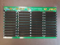
IMG_20220828_113341241.jpg
 
Yesterday I built George's nice Mini-Omnibus board. There is a lot of soldering involved. I really should build some solder fume extractor.

I hope to get the 6 mm acrylic base in the next day or two, but in the meantime will assemble and wire the 3 power supplies on an aluminium sheet.

Here is the result of yesterdays work:
Looks nice! Good job cutting the connectors, seems like a good amount of material on the ends to hold the single-pin shims. I cut mine a little to close and some of the single-pin shims were a bit loose, and had to carefully add glue so they stay in.

There's definitely a lot of soldering with all of those connectors! I use a 5 inch fan on my bench to blow the fumes in the other direction, but should probably get a real fume extractor.

When you get the 3 power supplies installed, I'm curious to learn if the duration of POWER OK inactive at startup is sufficient. We can lengthen it if necessary.
 
I have now mounted George's Mini-Omnibus on a 6 mm plexiglass (acrylic) sheet. I have also mounted the 3 Meanwell power supplies for +/-15V and +5V onto an aluminium board and fitted this into a old case. I wired in a fused IEC connector with switch and also the +/-15V and +5V to the Mini-Omnibus board. With a basic set of of PDP-8/e boards and Rolands M847 and 32K SRAM boards it nicely boots OS/8 and runs BASIC. Roland's M847 serves as a "front-panel" with the SW switch. Hopefully I get a real front-panel in the near future. I can do a lot just with custom programs loaded into Roland's M847.

Of course looking at it now I realise that the setup will be more usable for debug and repair with another physically distant Omnibus slot, so I will build another Mini-Omnibus board with initially just a single Omnibus slot connected via four ribbon cables to the current setup. This will make the board to be debugged much easier to access.

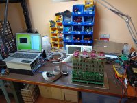
Here are a few photos (click on the photos to see the full size version):

IMG_20220901_210736000.jpg
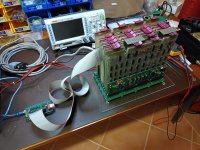
Above is my messy work bench with power supply, RX01 emulator and Mini-Omnibus.

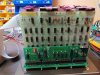
IMG_20220901_204516341.jpg
Close-up of the Mini-Omnibus setup.

IMG_20220901_210620020.jpg
Power supply front.

IMG_20220901_204443357.jpg
Power supply back.

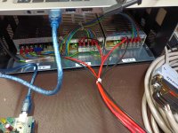
IMG_20220901_204342477.jpg
Mini-Omnibus and RX01 emulator.

IMG_20220901_204507608.jpg
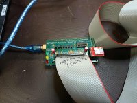
Close-up of Don North's original RX01 emulator. I ran out of PCB of Roland's version, so I built some more trying Don's version.

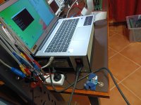
IMG_20220901_204422743.jpg
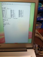
Finally above is a screen shot of OS/8 running BASIC.

I am quite happy with this setup and with a second one-slot Mini-Omnibus it should become a very useful debug & repair platform.

Tom
 
looks great - could you maybe list the pdp 8 boards you used?
From front to back:

Roland's M847 boot loader
M8330 timing board
M8310 major register control
M8300 major registers
M837 extended memory and timeshare control
M8357 floppy controller
M8655 UART
32k SRAM
empty
M8320 bus loads

There is one empty slot which will be taken up by a front-panel board if and when I get one.
 
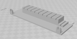
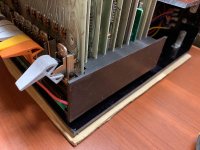
Got around to it eventually... there's a mini card guide accessory 3D print model available for the Mini Omnibus Backplane. It bolts onto the right side to hold the boards somewhat steady and is held in place by two of the existing mounting screws. The files are in github and have the prefix "Mini Backplane Card Guide": https://github.com/G-Wiley/Mini_Omnibus_Backplane

Mini Backplane Card Guide rendering.png Mini Backplane Card Guide photo.jpg

This version has an offset in the first slot to accommodate a Progammer's Console/front panel board. There's also a version of the card guide without this offset with "10 same" in the filename.
 
Looks good! Thank you. I'm curious as to how you printed(? they appear to have an unusual texture inconsistent with a simple 3D printer) those switch handle replacements. I have a pair of incomplete front panels (previously scavenged by former owners, alas) from which I think that I can re-construct one functional front panel, but I'm completely berift of switch handles.
 
Looks good! Thank you.
Thanks!
I'm curious as to how you printed(? they appear to have an unusual texture inconsistent with a simple 3D printer) those switch handle replacements.
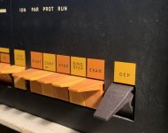
The switch handles are Vince's design, switch-vrs-mm.stl, that I sent to JLCPCB to have printed. They're about $1.10 each plus shipping. The material is PA12-HP Nylon, for a little extra strength. This gray one is from the first order. I got a second batch printed in black that look much better.

The gray ones absorb oil from fingers and accumulate marks after some use. We had a discussion about that a while back on the DEC forum and there were recommendations about coating or painting the switches. I haven't tried any of that yet.

Here's a photo of a black one installed on the PDP-8/L, looks much better than gray, IMO:
black deposit switch cropped.jpg

I have a pair of incomplete front panels (previously scavenged by former owners, alas) from which I think that I can re-construct one functional front panel, but I'm completely berift of switch handles.
I have a similar situation. The printed switch handles were key to repair a spare front panel that is now functional enough for testing boards in the mini backplane.
I'm looking for a couple of the momentary switches to solder into the Addr Load and Extended Addr Load positions for another front panel.
 
Though I haven't printed switch handles I have printed things that need a fair amount of strength. For out and out strength I use PLA infused with carbon fiber.

I haven't printed any switch handles but I would be glad to print some for someone if I have the colors you want in stock.
 
Though I haven't printed switch handles I have printed things that need a fair amount of strength. For out and out strength I use PLA infused with carbon fiber.

I haven't printed any switch handles but I would be glad to print some for someone if I have the colors you want in stock.
I need a complete set (21), alas, which I imagine might be more than you intended to offer! If not, then PM me and perhaps we can work something out?

Of course the 8/e standard colors (dusky-yellow and modest-orange) are highly desirable, else something neutral that would serve as a good base for future coloration. Pragmatically I doubt that I'd try coloration and would stick with whatever filament color is used. Would be satisfied to simply get the ridgeless look that @gwiley demonstrates.

@gwiley points out that in his experience "gray ones absorb oil from fingers and accumulate marks after some use" and recommends black. He appears to only have a single handle replaced, and that in a unique position. So that does appear to "work" visually. Alternating colors would help with "registration" of handles to positions in the two long banks. However, the Intersystems DPS-1 "gets by" with a single modest-orange shade across all of the banks. Do you carry "modest-orange" :-}?
 
The switch handles are Vince's design, switch-vrs-mm.stl, that I sent to JLCPCB to have printed. They're about $1.10 each plus shipping. The material is PA12-HP Nylon, for a little extra strength. This gray one is from the first order. I got a second batch printed in black that look much better.
Thanks for the JLCPCB suggestion; I've looked at https://jlcpcb.com/3d-printing and I see that "dyed black" and "natural gray" are the only two choices for "MJT (Nylon)". I don't see any ridges from the print-layering. Is the photo just deceptive or are they really as smooth as injection-molded?

I'm looking for a couple of the momentary switches to solder into the Addr Load and Extended Addr Load positions for another front panel.
Dug out my two front panel modules and refreshed my memory regarding why my two-to-one problem isn't anything like a slam dunk :-{. The fundamental problem is that the modules are of different generations and thus aren't component-interchangeable in critical regards, sigh.

The one in relatively good condition is older-generation (5009056D; rubber-stamped "APR 2 - 1971") with socketed bulbs (several broken or burned out) and the magnetic selector switch (missing shaft; one broken reed switch). I had previously unknowingly acquired (luck!) the light-shield bar that is used with it.

The other in poor condition is newer-generation (5009667D; rubber-stamped "APR 7 - 1972") with LEDs (many broken; one light-shield bar missing), the physical rotary switch, a patch-area on the upper-left including an unmarked DIP16, one rusted-leg TI DIP, wide-area mild verdigris of uncertain origin but quite disconcerting, and many missing slide-switches. So it's the presumptive parts donor module although I could conceivably hack-repair it for test-bench use, in which case I'd probably have to rewire the slide-switches to use modern(ish) bat-handle or similar toggle switches. Unfortunately there's no possibility of transplanting the mechanical rotary switch over to the earlier module due to the much larger footprint.

So my critical-path problem to a durable front panel is how to repair the magnetic selector switch (bulb replacement is a more doable challenge). In particular it's not at all clear how to replace the missing shaft as the entrance hole is round, not keyed by a flat. Peering deep into the opposite end against the PCB I think that I'm seeing on-end (_not_ circumferential) castellations which I presume are intended to interdigitate with a matching set on the shaft -- and that the metal(?) shaft is simply friction-fit through the entrance hole and down against the castellations. I guess that whomever originally disarticulated this module pulled the shaft out with the knob :-{. So in addition to trying to match the original reed switch I need to figure out how to manufacture a replacement shaft. Alternatively I'd need to find a modern SP5T rotary switch with the correct angular displacement that will form-fit the PCB and front-clearance.
 
Thanks for the JLCPCB suggestion; I've looked at https://jlcpcb.com/3d-printing and I see that "dyed black" and "natural gray" are the only two choices for "MJT (Nylon)". I don't see any ridges from the print-layering. Is the photo just deceptive or are they really as smooth as injection-molded?
I've used a slightly older sintered nylon fab for prints, but not yet used JLPCB. Even so, I believe that after the fusion step, a "bead blast" is used to clean the un-fused powder from the part. This would impart a uniform matte finish to the part.

The absorbency issue has to do with the tiny voids between the fused bits, making the part porous rather than the impermeable result you'd get from injection molding. Basically, the same reasons that make the surface matte also make it have a lot of surface area and can wick in the dirt.

So, to answer your question, I'd expect a surface like fine sandstone, except plastic. Layering should be nearly invisible, if the blasting has been effective. I've had sintered nylon parts made in the USA arrive still dusty and with a hint of the "machining" remaining, though. (Hopefully the new processes/printers have cleaned that up.)

Vince
 
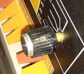
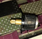
Its simple knurled shaft that press fits into switch. Knurled end 0.191" diameter
Amazing! Thank you for the close-up photos. After some cleanup with a toothpick I can now see the matching interior knurling in mine. Can you tell me the shaft distance from the shoulder where the knurling ends to the base of the knob?

It looks like the front-plate of the switch is simply held in place by the soldered-in reeds so disassembly should be straightforward. On closer inspection I think that I need to replace at least 3 reeds. There's no damage to the surrounding area or the intervening posts in the switch itself; I wonder how they managed to damage those glass reeds? It appears as if "standard" 2x14mm glass reed switches will *just* fit; I've ordered an inexpensive pack-of-ten from China for testing.

I wonder why DEC revised the design to replace the magnetic-reed switch with a conventional mechanical rotary switch? Perhaps just cost reduction ... or maybe the switch manufacturer ceased production?

For some reason I'm now reminded of winding cassette tapes with a "well-apportioned" pencil :->.
 
I've used a slightly older sintered nylon fab for prints, but not yet used JLPCB. Even so, I believe that after the fusion step, a "bead blast" is used to clean the un-fused powder from the part. This would impart a uniform matte finish to the part.

The absorbency issue has to do with the tiny voids between the fused bits, making the part porous rather than the impermeable result you'd get from injection molding. Basically, the same reasons that make the surface matte also make it have a lot of surface area and can wick in the dirt.

So, to answer your question, I'd expect a surface like fine sandstone, except plastic. Layering should be nearly invisible, if the blasting has been effective. I've had sintered nylon parts made in the USA arrive still dusty and with a hint of the "machining" remaining, though. (Hopefully the new processes/printers have cleaned that up.)

Vince
Thank you for the absorbancy explanation, as well as the general process description. That explains the pretty nice finish that I see, and for not an unreasonable cost. I wonder how well the shaft nubbins hold up in use?
 
Thank you for the absorbancy explanation, as well as the general process description. That explains the pretty nice finish that I see, and for not an unreasonable cost. I wonder how well the shaft nubbins hold up in use?
Pretty well -- the nylon is "tough", which is also to say that it's not as brittle as the cast ABS or whatever that the original parts are made of. I think the that means the nylon nubbins are more likely to get rounded over time rather than snap off.

Vince
 
Got around to it eventually... there's a mini card guide accessory 3D print model available for the Mini Omnibus Backplane. It bolts onto the right side to hold the boards somewhat steady and is held in place by two of the existing mounting screws. The files are in github and have the prefix "Mini Backplane Card Guide": https://github.com/G-Wiley/Mini_Omnibus_Backplane

View attachment 1252039 View attachment 1252040

This version has an offset in the first slot to accommodate a Progammer's Console/front panel board. There's also a version of the card guide without this offset with "10 same" in the filename.
Thank you George.

Until now I placed a piece of thin cardboard between the boards to prevent them touching, but the whole thing feels a bit fragile in particular the front panel.
Why did you chose to have to card guide only on the right side rather than on both sides? It should be relatively easy to just mirror the design.

Did you print the card guide yourself or did you use JLCPCB? What material was used for printing?

I sliced the STL file using Ultimaker Cura and it claims it would take 6 hours 53 minutes to print using 30 m of filament (80 grams). This is with 100% infill.
Likely my slicing parameters are wrong to make it so slow.

I have never printed anything this big on my Creality Ender 5.
 
Until now I placed a piece of thin cardboard between the boards to prevent them touching, but the whole thing feels a bit fragile in particular the front panel.
The front panel does wobble a bit in the mini backplane. However, I've discovered that I don't go to the switches much on the front panel since building the M847-Extended boot loader.

Why did you chose to have to card guide only on the right side rather than on both sides? It should be relatively easy to just mirror the design.
True, and I've been thinking about making one for the left side as well. However, that's been delayed because I've started designing a jig to support the front panel plus plexi-panel. A left-side card guide would be a quick project though.

Did you print the card guide yourself or did you use JLCPCB? What material was used for printing?
This one I printed myself. Santa brought me an Ender 2 v2 printer and I've been having some fun with that.
I used just black PLA filament to print the card guide.
Months ago I didn't think I wanted a printer because JLC was easy and can produce a higher quality part. That's true for complicated parts such as PDP-8 switch handles but having the instant result is a very convenient. But this is another topic.

I sliced the STL file using Ultimaker Cura and it claims it would take 6 hours 53 minutes to print using 30 m of filament (80 grams). This is with 100% infill.
Likely my slicing parameters are wrong to make it so slow.
I'm also using Ultimaker Cura for slicing. Used default parameters except set the wall thickness to 1.6 mm so the 3 mm thick mounting feet would be solid but the thicker parts of the guide would have some empty cells inside. I could observe these open cells while it was printing. I think it printed in about 5 hours. Total weight predicted by Cura is 42g, and the actual part was about the same, measured with my kitchen scale.
The printed part feels robust but not heavy.
 
Back
Top