BitWiz
Experienced Member
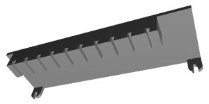
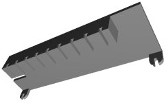
I took Vince's switch paddle and played with it until I could get it the best that I can on my Prusa MK3S+.
Here are the results:
https://drive.google.com/drive/folders/1ogop3aTsTOpLXn-rV4LReY2V4WLvuCEy?usp=share_link
This were printed standing on the tabs that slide over the switch on the circuit board and printed with supports with Prusa PETG orange filament.
I don't have the DEC colors but if anyone wants to send me the filaments in the DEC colors I will print them a complete set.