• Please review our updated Terms and Rules here

Model 1 video issues

homeline

Member
Joined
May 10, 2017
Messages
37
Location
S. IL
Good evening all. Been lurking around here in the back ground off & on for a few years. Mostly enjoy reading and learing about various systems. Not a stranger to vintage computing, and have acquired machines that I wanted when I was growing up. I am an IBM & Commodore guy, and up to now knew almost nothing about the TRS80 family.

First the backstory: Over a year and a half ago I scored a TRS80 Model 1 off Ebay. Suffice it to say it was nearly all but destroyed between the horrible pack job and UPS. Seller apologized profusely and issued full refund. Tossed it, still the boxes, in the corner. About 4 weeks ago I almost put it in the recycling bin. Decided against it for various reasons, and proceded down the rabbit hole.

Keyboard plastic was easily in a 100 pcs. Monitor case severly cracked in several places. But no damage to any of the internals, or the keyboard save for one missing key (funny how the gaping hole in the box did not allow any broken plastic to escape!) Expansion unit was unscathed. Of the 3 drives, only one broken latch. No software or manuals included.

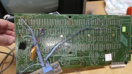
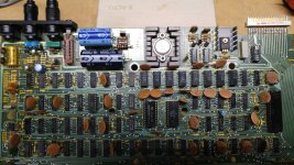
PS voltages checked out OK, so I fired it up...and nothing but scramble screen. After 30 minutes of cleaning contacts and reseating chips the darn thing came to life! Played around with it for an hour or more, absolutely no issues, even a rock solid stable display. I was floored. Have not hooked up EI or drives yet. As Bob said, baby steps.

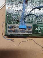
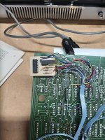
The problem came after I cleaned the circuit board and replaced keyboard cable. A very strange vertical sync problem. It has situated the top of the display area near bottom of screen. Done a lot of reading and watched several videos, but nothing I have found addresses this type of issue. I do have the tech ref manual, and have done some preliminary troubleshooting. Some things check out, some don't or just not sure. Just wanted to get some ideas before I start replacing the usual suspect chips.
Also, is it possible issue could be the monitor itself?

20220830_201958_resized.jpg
 
forgot to mention that adjusting the R22 pot does not fix.

just found a post by member Zoggins from Jan this year.
The output starts about 2 or 3 inches down on the screen and the cursor is somewhere below the screen. I verified its the computer not the monitor, but does anyone have any pointers on where to start looking?

i think i know direction to take now. My Z57 chip has been replaced in the past....looks like they used a welder to do it.
 
forgot to mention that adjusting the R22 pot does not fix

In my copy of the TRS-80 manual the vertical adjustment pot is R21, was R22 a typo?

The function of R21 is to control the rate at which the capacitor C26 charges, so if adjusting it is making no difference at all then I would start by just paralleling another capacitor of similar (doesn't matter if it's exact, just close will give you the info you need) onto the one in the board. If this restores the ability to adjust delay then you're good to go. Do this before you go unsoldering the chips because I suspect if that chip were dead you'd be getting no vertical sync at all, and therefore have a rolling display instead of a stable misplaced one.

FWIW, I'm noddingly familiar with this part of the Model I's circuitry because last year I was a glutton for punishment and bought myself a basket case Storage Wars Model I to play with, and it had issues with horizontal stability. (If you watch that video you'll find the punchline that the issue wasn't the capacitors in the video delay circuit that were the problem, it was the power supply basically proving half-wave AC instead of stable DC to the board that was wreaking havoc with the rate at which the perfectly good caps charged, but... I think your problem is easier than that.)
 
R21 is correct, that was a typo.

Adjusting the pot will roll it off the bottom back to just barely coming down from the top. Also had to adjust the v-hold on monitor in conjunction with cranking R21 fully to one side, to get image to stay still. In this way image is slightly fuzzy/distorted. Putting monitor v-hold back to approximate 'normal' setting makes for a clear display, but it rolls.

One possible cause of this issue is my carelessness with the wires on bottom/backside of board. I had sat the board flat on the bench when cleaning and re-seating chips. One or more of the wires from a mod done on Z56 had been pierced by a protruding pins on Z57. Did not catch this until after powering it up.

Also, are the extra mod boards the lower case & Level 2?
 

Attachments

  • 20220830_205805_resized.jpg
    20220830_205805_resized.jpg
    1.7 MB · Views: 22
Level II is the big satellite board with the ribbon cable that terminates in one of the ROM sockets. That board that’s visible in your photo… I’m not sure what that is. It looks excessive for a lowercase mod, those were usually just piggyback jobs. I will vaguely guess it’s either a speed up board or a CP/M mod, but I can’t tell from that shot.
 
I'll get a better photo of small board. Not sure about lowercase, as anything typed is uppercase. Using shift made no difference. Does it need some software as well for lowercase?

Here is the top side of the main board.

At the moment getting the screen back in proper form is top priority.
 

Attachments

  • 20220828_201240_resized.jpg
    20220828_201240_resized.jpg
    542.6 KB · Views: 18
That look like a late, 2 rom only, v1.3 motherboard. That's a very complicated mod for the larger daughter board. I'd also guess a re-mapper for CP/M. Might get a good pic of the daughterboards.
 
That look like a late, 2 rom only, v1.3 motherboard. That's a very complicated mod for the larger daughter board. I'd also guess a re-mapper for CP/M. Might get a good pic of the daughterboards.

Yeah, I assumed the satellite ROM board for earlier models was just out of frame in the earlier picture, but I guess you meant the tiny board with the two layers of double-sided tape under it. Actually seeing the top of it would help a lot for guessing. ;) I would chuck out it could be an Archbold speed-up board, but that's literally a blind guess.
 
The 2 chip ROM does fix the problem the XRX does, but someone may have replaced the older ROM board and didn't realize the XRX isn't needed anymore.
 
Some money shots of add-on boards.

The larger one has the power LED light. You can also see an unconnected wire. One end is soldered to a diode shown on this board, while the other end exited out the back of console and appears to connect to a similar wire exiting from EI box. It was looped around a stand-off inside the case, acting as a strain relief. Guessing this is one form of a buffer cable I have read about.
 

Attachments

  • 20220902_200111.jpg
    20220902_200111.jpg
    1.4 MB · Views: 18
  • 20220902_200147.jpg
    20220902_200147.jpg
    1.1 MB · Views: 17
Some money shots of add-on boards.

The larger one has the power LED light. You can also see an unconnected wire. One end is soldered to a diode shown on this board, while the other end exited out the back of console and appears to connect to a similar wire exiting from EI box. It was looped around a stand-off inside the case, acting as a strain relief. Guessing this is one form of a buffer cable I have read about.
That second board was in the TRS-80 of the Adrian video the other day, except it was stickied to the top of the keyboard. Good pic of it, I remember the 4040 is a big ripple counter, now I'm totally confused what the board does.
 
I stand corrected, did some digging and it’s the later XRX-III mod. Which technically shouldn’t be required with the two ROM set, but is compatible with it unlike the earlier 4-wire XRX.
 
Progress has been slow on troubleshooting, as I was out of town all weekend. But making some strides. Using pages 31-33 & 69 from the tech manual as a guide, have Z32 as a strong possibility of being bad. All the output frequencies on Z32 are off by a wide margin. The output on pin 11 is supposed to 60Hz, but only reading 41Hz. The input on pin 14 is spot on at 660Hz. All the other frequencies in divder chain (VDRV & HDRV) check out.

Appears one of the outputs of Z32 is fed back into itself, perhaps indirectly from Z66?? So at this stage I think i am going to replace Z32.

My scope skills are very basic, but i do get a very simliar video output reading compared to what is shown on page 43, but the vert timing looks off. The question is, could something downstream in the sync mixing affect output of Z32?

In a one step forward, two steps back ordeal, I fried one or more of the RAM chips. In a foolish move, when I checked/adjusted voltages I inadvertently spiked the 12v line beyond 13 volts for a brief moment before catching it. You guessed it...bye bye RAM! In a semi-stroke of good luck, I had a stash of more than 30 of the 41016 chips from some computers I parted out more than 25 years ago. But at least 2 of them have already died, most likely due age and repeated powercycling from testing things. Have pulled them all for time being.
 
In my copy of the TRS-80 manual the vertical adjustment pot is R21, was R22 a typo?

The function of R21 is to control the rate at which the capacitor C26 charges, so if adjusting it is making no difference at all then I would start by just paralleling another capacitor of similar (doesn't matter if it's exact, just close will give you the info you need) onto the one in the board. If this restores the ability to adjust delay then you're good to go. Do this before you go unsoldering the chips because I suspect if that chip were dead you'd be getting no vertical sync at all, and therefore have a rolling display instead of a stable misplaced one.
Forgot to mention, I did try this. No change in display.
 
So I ordered some chips & DIP sockets and finally got around to replacing Z32.

No change in symptoms. Still 41Hz on pin 11. So something is affecting the output. Before I replace Z57, will do some more sleuthing.

Eudi....great videos. Watched them all on your Mod 1, and various portions multiple times. Very informative and helpful.
 
Eudi....great videos. Watched them all on your Mod 1, and various portions multiple times. Very informative and helpful.

Thanks! That Model I repair was a big learning experience for me. Biggest takeaway is I need to remember to break out the oscilloscope first thing instead of faffing around with just the voltmeter and whatnot. Just because a voltage looks okay on the VM doesn't mean it's *actually* okay. Bleah.

Coincidentally enough I just pulled that Model I off the shelf to poke at this morning. It's been sitting for about nine months and it's already cranky again. Horizontal hold was glitching, and I was getting the wrong characters when I tried to engage the lowercase mod. (My machine is an early-ish D-board unit with a number of homemade modifications.) It looks like the latter problem was a glitchy short in the really ropy soldering of the lowercase mod (the guy who did the work on this machine may have actually been worse at soldering than I am, which is a bit of an achievement), and some contact cleaner on the adjustment pots seem to have fixed the horizontal glitching. For now. These poor things are getting a bit brittle in their golden years.
 
congrats on doing a repair to the crt that arrived mangled. I too bought a model 1 monitor off ebay and had it arrive smashed badly from a terrible packing job.. even though the seller wasnt all that far from me

Once you iron out the issues a little plastic automotive body filler, a sanding and a paint job.and it will look like a million bucks.

Yup...a bit of soldering iron action along with some epoxy stabilized everything. I'm no stranger to the rattle can restortion method.

I really lucked out for the keyboard console....managed to score a NOS one from Ebay recently. No decals, never even a screw in the screw-bosses. Just a few minor scuffs and scratches from storage over the decades. Quite fitting really for this dinosaur.
 
Back
Top