• Please review our updated Terms and Rules here

Model I question

mdh

Experienced Member
Joined
Dec 9, 2021
Messages
139
Location
North East Ohio
So I have a model I with the pigtail connector coming out of the expansion area. Do I need to have an expansion interface with the connector too? Or can any expansion interface be used? Also, need to take pictures - its warranty seal is intact!

Haven’t booted it up yet, don’t have a power supply. Will be building that in a month or so...
 
Hello mdh; there is a lot of good information on the TRS-80 Model 1 and the EI on this site. As to the various revisions to the EI and the Keyboard unit, I believe there were four...
1) Original with no mods (connected with ribbon cable)
2) Powered buffer box between the two units (used 74LS244's to buffer the signals PLUS a modified ORANGE power wire in the EI)
3) DIN cable mod (route memory RAS, CAS and MUX over DIN cable PLUS a modified ORANGE power wire in the EI for the older buffer box)
4) New re-design of the EI that generates RAS, CAS and MUX on the EI itself. EI board looks different with memory relocated from original.
Care must be given to the ORANGE power wire as Radio Shack used a modified GND trace in the EI to route the new power to the buffer box.

The DIN cable modification is described here..."TRS-80 Model 1 Expansion Interface Buffer Mod.pdf" (http://vintagecomputer.ca/files/Radio Shack/TRS-80 Model 1 Expansion Interface Buffer Mod.pdf) Buffer MOD

Photo's of the EI modification and discussion is here..."TRS-80 Model I Expansion Interface" (http://knut.one/m1ei.htm)

As to the expansion interface power supply TRS Ian has one on Ebay (shipped from Australia) or you can build your own. I posted info for doing this on-site if you search for..."Expansion Interface Power Supply" 2/27/19 by Dawsoca. Expansion Pwr Supply
TRS Ian's unit works best when using 240VAC with the monitor on top of the EI. Wavy lines in the display are visible. In the US, the 120VAC units do not seem to have this problem. Mine works fine and powers the keyboard unit too.

>>> Charles
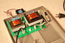
EIpwr.jpg
 
Hello mdh,

I'm sorry but I don't know what "MIRE" means....Model 1 Revised Expansion?? When you open up your expansion unit you will be able to tell which version you have and what modifications have been done to it. The important thing is to verify if the Orange +5V wire is present in the EI. This Orange +5V wire from the EI will be wired to Pin#37 of J2 going back to the keyboard unit which has Pin#37 as a GND. So this would short the +5V in the EI to GND if connected without the buffer box.


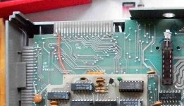
I3ISC9P.jpg


From what you have said, your keyboard unit has the DIN plug which would indicate it has the RAS,CAS and MUX signal traces cut on the circuit board and routed through the DIN cable. It was more than likely mated to a Modified EI with a DIN plug and a buffer box.

To get all this to work, you will have to either modify your EI or reverse modify your keyboard unit. If you have a revised new EI, you will still need to reverse modify your keyboard unit as the RAS signal on Pin#1 of J2 in the EI is still required.

The best suggestion would be to get a copy of the expansion interface service manual and trace out the signal lines to see what you have.

On my expansion interface from Ebay, it had the DIN plug and Orange wire mod. I removed the DIN connections from the EI as my keyboard unit did not have them. I connected the keyboard to the EI using a buffer box and it works fine for me.

>>> Charles
 
Does anyone have any documentation about the changes made to the model I side for the pig tail? Did it cut any traces on the expansion connector?
 
Sort of a general gripe about this situation, but I have a Model I/EI pair with the buffered cable, and they've been giving me tons of grief which I suspect is in part due to the DIN plugs being oxidized/rusted. Instead of messing with trying to replace the DIN plugs and otherwise make the known unreliable thing reliable I've been strongly considering building a replacement for the board inside the buffered cable that has the buffers for the peripherals in the EI, but holds A15 low on the expansion interface side (so the 32k in the expansion interface would never be enabled) and incorporates a 32K SRAM chip to use instead. Static RAM won't care about CAS/RAS/MUX so it shouldn't matter if the DIN cable is even connected, and if I use HC logic for the buffers adding the RAM shouldn't make it draw much if any more power than the original board.
 
Does anyone have any documentation about the changes made to the model I side for the pig tail? Did it cut any traces on the expansion connector?
The only changes in the keyboard unit involve adding the twisted pairs on the DIN connector.
 
The only changes in the keyboard unit involve adding the twisted pairs on the DIN connector.
This would seem to suggest one could indeed run a modified keyboard with an unmodified E/I as it would be the same as running the pair as though the keyboard were also unmodified. Did the last version of the E/I require a buffered cable? The reason I ask is because I have bought a keyboard with the DIN connector, and the last version of the E/I. Specifically, were any traces cut in the keyboard for the DIN connector mod? Were any jumpers installed? I know it was asked before. Thing is, the first answer in this thread was that one could NOT use a DIN modified keyboard with an E/I which didn't have the DIN mod, and then someone up voted that response. That response conflicts with the answer that there were no traces cut or jumpers installed. Moreover, the mod documentation I downloaded appears to only have cut etches and jumper wires in the E/I. I'm hoping there's a former RS tech familiar with these mods which will give a qualified answer.
 
Last edited:
Back
Top