Chuck(G)
25k Member
...or any other standard floppy controller with an external drive connector (it works fine on a Compaticard, for example).
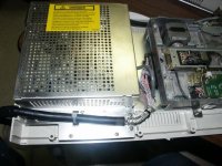
First, take your 4869 apart. Note that there are 8 screws on the bottom and that 2 of these are tamper-proof Torx-head screws. Fortunately, it's easy to find screwdriver bits for these tamper-proof screws, which makes them not so tamper-proof. Note which holes belong to which screws. The Torx head screws are longer than the others and will enlarge the other holes needlessly, leading to "loosey-goosey" screw fitting.
Remove the shield that bridges the drive shield and the power supply. 4 phillips-head screws. Put them where you can find them. You'll see that the drive cable is a standard edge connector type, pull it off the drive. Remove the small clamp that holds the cable shield to the baseplate (2 phillips-head screws) to give yourself some room to work.
For this example, I also cut the cable tie that tethers the cable to the base and removed the entire cable. You don't have to do this--but see my note at the end.
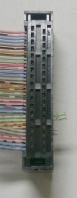
So, now you're looking at a cable with a connector that looks like this:

Taking a couple of small screwdrivers remove the strain relief from the connector--you'll note from the photo that this clips over the cable retainer with two metal ears--using the corresponding hole on the opposite (edge slot) side of the connector, gently pry each metal ear outwards and lift each end of the relief so that the strain relief comes free (this is a little tricky):

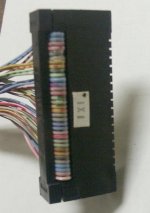
Now, unfold the cable and using your small screwdrivers and the access hole, remove the retainer, leaving the cable attached to the connector:

Now, take a small X-acto knife and cut between the green and gray wire pairs and the other wires and gently pry them up as shown below. Be careful not to cut into any wires, just cut the webbing between them. Free the two pairs so that you can exchange them on the connector without twisting each pair.

Exchange the position of the gray and green pairs and gently press them onto the connector pins, so that the little contact edges hold them.

Post continued below...
First, take your 4869 apart. Note that there are 8 screws on the bottom and that 2 of these are tamper-proof Torx-head screws. Fortunately, it's easy to find screwdriver bits for these tamper-proof screws, which makes them not so tamper-proof. Note which holes belong to which screws. The Torx head screws are longer than the others and will enlarge the other holes needlessly, leading to "loosey-goosey" screw fitting.
Remove the shield that bridges the drive shield and the power supply. 4 phillips-head screws. Put them where you can find them. You'll see that the drive cable is a standard edge connector type, pull it off the drive. Remove the small clamp that holds the cable shield to the baseplate (2 phillips-head screws) to give yourself some room to work.
For this example, I also cut the cable tie that tethers the cable to the base and removed the entire cable. You don't have to do this--but see my note at the end.
So, now you're looking at a cable with a connector that looks like this:
Taking a couple of small screwdrivers remove the strain relief from the connector--you'll note from the photo that this clips over the cable retainer with two metal ears--using the corresponding hole on the opposite (edge slot) side of the connector, gently pry each metal ear outwards and lift each end of the relief so that the strain relief comes free (this is a little tricky):
Now, unfold the cable and using your small screwdrivers and the access hole, remove the retainer, leaving the cable attached to the connector:
Now, take a small X-acto knife and cut between the green and gray wire pairs and the other wires and gently pry them up as shown below. Be careful not to cut into any wires, just cut the webbing between them. Free the two pairs so that you can exchange them on the connector without twisting each pair.
Exchange the position of the gray and green pairs and gently press them onto the connector pins, so that the little contact edges hold them.
Post continued below...