• Please review our updated Terms and Rules here

My custom TRS-80 lowercase mod

Bruce Tomlin

Experienced Member
Joined
Jan 6, 2010
Messages
340
Location
San Antonio, TX
The recent talk about lowercase on a TRS-80 reminded me to finally document something I did back in the day.

There were multiple versions of the MCM6670 character generator chip used by Tandy. Some of them had "squashed" lowercase that stayed in the 5x8 matrix. But some of them had descenders that would look perfect if lowered by two pixels. I think there also one with an extra copy of uppercase in the 00-1F range because of the way the video worked. As far as I know, all of the character generator chips were custom in having the arrow characters at 5B-5D, but Tandy didn't care about the other characters until people wanted lowercase.

My specific chargen chip is marked "3108001", which is the Tandy part number listed in the Technical Reference Handbook. Its date code is 7806. I don't know if a different part number was used for other revisions. It has the standard MCM6670 data sheet character set except for the arrows.

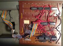
This is the outboard mod that I made which moves descenders down by two pixels. I'm pretty sure that originally it was just the first two boards, then I had a need for the third board. I really have no idea why I needed it. It seems to specifically switch between character code 01 and 03 under certain conditions on certain scan lines.

The basic idea is to first detect the descender character codes with U3/U4, then subtract two from the scan line address with U2. I did the detection with a demux/mux (and a few diodes for a fake gate), and the subtraction with a 7483 full-adder chip hard-wired to add either 0000 or 1110. Adding 14 (1110) is a 4-bit two's complement negative 2. Adding negative two is like subtracting two. And for what it's worth, that adder chip always ran warm to the touch.

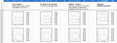
The seven characters that need lowering are:
Code:
        , ; g j p q y
I see 8 connections between U3 and U4, so I probably also added the underline to that set.

After a few years it was starting to get a little bit unreliable being on a solderless breadboard, so I made this more permanent version. It was lighter too, so even less chance of an "accident".

I spent all day tracing it out, and here is the schematic that I got from it.
 

Attachments

  • IMG_20220701_151840551..jpg
    IMG_20220701_151840551..jpg
    256.2 KB · Views: 19
  • trs-lc.pdf
    154 KB · Views: 13
Ah, now I remember, one of the character generator ROMs had the lowercase 'a' raised up by two lines. And now I realize that may be the eighth term I added to the descender detection.
 
Bruce,
in looking at the Character Generator's that I decoded, I believe the COMMA wasn't one of the
characters that required lowering. The comma's all appear to be properly placed. It was likely
another character, as lots were displaced by one pixel, but the FLYING a was displaced by
two pixels.

I've decoded several Model 1 Character Generators, including a newer Model 1 with the 1.3 Version
ROM and an updated Character Generator (IC number not available), my KSG Tech LC Adapter Board,
and a Model 1 with a 8046673 Character Generator.

It's interesting that you did the placement via hardware, while I just moved the required character(s)
a pixel or two for proper placement and burned a new EPROM. That was many decades ago.

Larry
 

Attachments

  • Model 1.png
    Model 1.png
    63.2 KB · Views: 9
Nice!

When I designed my Model 1 clone I simplified the video generation circuitry by defining all characters (including the 64 graphics ones) entirely in the character ROM. The bottom four pixel rows of the non graphics characters aren't hardware blanked either. This essentially makes the full 6x12 pixel grid for every selectable character definable. This is a bit wasteful of ROM as it requires 16 bytes for each character, but only uses 12, but that doesn't really matter. I page select my ROM with a switch to allow a choice between a duplication of the original character set and the upgraded one.

This kind of ROM swap and rewire would be the ultimate character generator upgrade for an original machine, if you're in to custom designing your own character sets.


1656767299323.png
 
Last edited:
This essentially makes the full 6x12 pixel grid for every selectable character definable. This is a bit wasteful of ROM as it requires 16 bytes for each character, but only uses 12, but that doesn't really matter.

Not really useful for the original machines, but FWIW on a home brew video system I‘ve been playing around with I cooked up a method to do characters an arbitrary number of lines tall that doesn’t waste any memory. (I haven’t taken it further than a breadboard yet, but as is its ‘demo mode’ includes switching between TRS-80 and Commodore PET modes.) It’s reasonably easy to implement but it does require some… lateral thinking.

Long and short of it, I shuffled the address lines. On a normal character generator people treat the “character address”, usually 8 bits, separately from the row address, and when you get a dump from a character ROM the row addresses effectively become the lowest address lines of the combined set. IE, on a typical 3-bit row generator if you step through the memory image the first 8 bytes will be the first character, second 8 bytes the next, etc. Which does mean, yeah, even a 9-line character set will mean 4 row address lines, thereby doubling the memory footprint even if you only use that one extra row.

What I did, since I’d optimized the underlying system for linear bitmapped graphics anyway, is flipped it so the line address is added at the *end* of the address. So in my memory representation the first 256 bytes in the character set memory is the first row of every character, the next 256 the second line, etc. By doing this you can see that an 8 (or 6) x 12 character set now does only take 12x256 bytes, or 3k, instead of 4K.

Anyway, it definitely doesn’t matter, for sure, if you’re just making a hardwired character set video system. I came up with this system as a solution for simplifying switching between ‘tiled’ (character) modes and linear bitmap graphics with as few parts as possible, and the memory saving is sort of a bonus. (the character glyphs can live in either ram or rom, so the memory saving is significant when the character memory is also in CPU address space.)
 
I believe the COMMA wasn't one of the
characters that required lowering
It wasn't required, but it did look nice. The way I did it only needed a few extra wires to add the comma, and fixing the broken 'a' basically came for free. And it gave me a free puzzle decades later. I think I still mixed up a connection or two because I couldn't quite make a table of the decode function last night.

And yes you do save some chips by using a massive EPROM, but that's not something you could do in 1980, especially as a high-school kid. It also doesn't fit into the 18-DIP position on the board.

I, er, went through more than one main board back in the day. At one point I had reverse video uppercase in the C0-FF area. There were so many times when I'd drop in half a 7474 to fix some dot timing. Then I completely screwed it up and went back to just lowercase. But that's how I got familiar with the different character generator chips. The broken-a version was just where I ended up.
 
And yes you do save some chips by using a massive EPROM, but that's not something you could do in 1980, especially as a high-school kid. It also doesn't fit into the 18-DIP position on the board.


You could have, but the EPROM would have burnt a hole in your wallet and you would have at least needed access to the equipment required to burn the devices. Not trying to detract from workarounds that were viable ~40 years ago by segueing into stuff easily and cheaply done today.

Just out of curiosity I did some internet searching and found the "Gendon3" character ROM upgrade kit. It gives a character set with 3-line descenders using a 2716 2KB EPROM. 2048/16 = 128, so I guess this upgrade works up defining all 12 lines of all characters aside from the logic-generated graphics ones in the 2716.
 
On re-checking everything, I found one minor transcription error. Then I tried to decode the function of the ghetto PLA, but I still couldn't find the decode for "j", which was even out of range for the 7442.

I noticed I had a monitor lying around, so I tried to power up the old thing to see what the characters looked like. No power supply in the TRS-80 box, and only one power supply in my EI box. And the power supply didn't work. And it had been opened before. And the fuse was blown. I "hot-wired" it with a strand of copper wire, and got it to power up. But the video was just a bunch of 1-inch wide white lines with no sync. Getting the thing working again will have to be a future project.
 

Attachments

  • trs-lc.pdf
    174.9 KB · Views: 9
Back
Top