• Please review our updated Terms and Rules here

Need help with TS2068 repair

ianoid

Experienced Member
Joined
Jul 23, 2013
Messages
76
Location
Austin, TX
Hello all,

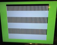
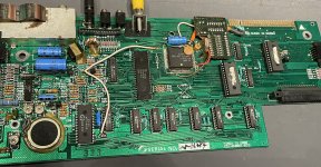
I have a 2068 that shows these bars. I figured I'd replace any bad RAM and socket it. Unfortunately I pulled up a few traces but I put (yellow) bodge wires best I could between the RAM legs with the bad traces. After confirming all the RAM is good, what is the next step to troubleshoot the bar screen? Also, should most of the RAM be in line? It seems like 4 of the chips have mostly continuity between the pins and two have fewer pins in continuity. I looked at what I thought was a schematic (TS 2000 board) and it seemed like most of the pins should be continuous between all 6 RAM chips. The bar screen looks more or less the same after getting all working RAM installed.

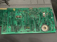
I also recapped the board.

Besides the RAM, what would be the next move to getting it to work?

I am using a spec matched modern PS instead of the original one I have for it.
 

Attachments

  • IMG_3945.jpeg
    IMG_3945.jpeg
    2.6 MB · Views: 17
  • IMG_3946.jpeg
    IMG_3946.jpeg
    2.9 MB · Views: 18
  • IMG_3947.jpeg
    IMG_3947.jpeg
    3.6 MB · Views: 18
I don't recommend recapping the sinclairs at all unless you really know what you're doing ( I have repaired many and very few capacitors need replacing - you can check them with a thermal camera. Most are within operating spec - they don't usually have the problems that C64s have ). I don't know about the TMS models though. Very little in the way of capacitors look like it would affect operation nonetheless in the picture shown.

Anyway, if it's not starting, suspect the RAM still isn't right. Look for broken tracks and shorted tracks. Ideally, get hold of a diagnostic cartridge - You might be able to use a Spectrum one. This will tell you what is faulty a little more than the stock rom.

Next, work your way through the pins one by one. Get a schematic and some pinouts and slowly and carefully check each pin for any shorts to pins around it and on the other side of the RAM chip adjacent to it. Around 5 pins in total to check for each pin on the chip. Then check each of the pins correctly connects back to the main square chip. I've never really played with one of these machines, so that's the same generalised information I'd use to troubleshoot a sinclair machine.

Between slowly tracking everything to confirm all the tracks are good, and a diagnostic rom, you should find a solution :)

Regards
David
 
The regular repeating pattern on the display makes it look like either a memory problem, or a problem with the ULA (the square chip). The soldering around the ULA looks particularly bad, I'd check all the pins and make sure none of them are shorted to the pin next to them.
 
From a sinclair perspective, you're probably seeing the ram default memory contents. If the OS can't boot and clear the ram ( it tests for an error ) then it's going to fail right at the start and lock up, and so nothing happens. So it's probably a case of the CPU not being able to read/write the ram reliable. Which is why a diagnostic cartridge may be helpful as they run entirely out of the ROM.
 
I ordered a Spectrum Diagnostic cart from the UK, so hopefully that will do the trick. I appreciate the advice and suggestions.
 
The regular repeating pattern on the display makes it look like either a memory problem, or a problem with the ULA (the square chip). The soldering around the ULA looks particularly bad, I'd check all the pins and make sure none of them are shorted to the pin next to them.
Given that the memory is socketed, might be worth rotating the memory around and see if the pattern changes. As far as I can tell U6 and U7 are the lower 16K and contain the screen data.
Try doing a swap for U12+U13 or U17+U18.
 
I just recently got a 2068 myself. I put 15v through it on my bench power supply since it didn’t come with one and it booted but it had a wavy distorted video signal and heard some whining from the speaker maybe? Watched a video Adrian’s digital basement and he had similar behavior:


He was not getting color when he lowered voltage to 9 but image quality was much better. I confirmed it needs 15v to get color but didn’t know if the poor composite signal was common with the computer. If it is is there any way of cleaning up the signal? I have seen replacement regulators for it but don’t want to mod too much if there are other options.

Ianoid did you ever get yours up and running?
 
One thing to keep in mind about the Timex 2068: it was a departure from the spectrum to make it more competitive in the US where it was intended to go up against the popular C64. It has, for example, unique built-in joystick ports that the spectrum never got, a different sound chip, and a modified BASIC ROM that allowed direct access to these additions.

A good source for hardware-related info is this book:

https://archive.org/details/manualzilla-id-5878266
Thanks for the info! All of those modifications unfortunately made it completely incompatible with all of the spectrum software. I think it would have been a slam dunk if it could also play speccy games without that very rare spectrum emulator cartridge
 
I wouldn't say "completely incompatible". The compatibility depends on the degree to which the Spectrum software relies on the addresses of ROM routines... which, honestly, I'd have expected to be low to nonexistent for the average machine code program, since the ROM is mostly a BASIC interpreter, not really an operating system. (And BASIC software, ironically, doesn't rely on those addresses at all, so it's already (mostly?) compatible.)
 
In the later years there was a bit of a battle between the software producers and the pirates who were by then using hardware 'snapshot' gadgets to freeze and capture the program code after it had been loaded in by one of many custom loaders. These typically swapped out the internal ROM of the Spectrum and replaced it with one which was mostly the same as the Spectrum ROM but had some of the code altered to support the operation of the 'capture' gizmo.

As a response to this, the software producers started to use the original ROM code as a kind of 'Key' against which to encode the program code onto tape and to reconstruct it when reloading it from afterwards, the idea being that the program would then only load correctly if the machine's ROM code was unaltered. If there was any altered code in the ROM, this process would fail.

This was a good idea as far as it went and as long as the ROM code was never changed by Sinclair, but it meant that Amstrad's unnecessary vanity in changing the original start up prompt from 'Sinclair 1982' to 'Amstrad 1986' in the 48K mode of the +2 machines broke a lot of tape loaders...
 
Back
Top