• Please review our updated Terms and Rules here

Neglected PET needing some love

Unfortunately, the adapter can't change the horizontal frequency. To do that you will have to modify the PET CRTC programming in the EDIT ROM, and that (in all probability) will make it incompatible with the PET firmware (but this is only a gut feeling).

Dave
 
Most composite monochrome CRT VDU's of the vintage computer era (except those types that don't have internal H scan oscillators made specifically for computers like the IBM5151) are set up for either 50 or 60Hz vertical syncs and 15.7kHz (approx) Horizontal syncs.

Inside the CRT VDU, the composite signal has the H and V syncs separated off and fed to the H & V scan oscillators, to pull them into lock (synchronization with the sync frequency). The H osc won't come into lock, unless the sync frequency is close to what it is expecting. A VDU made to lock to a 15.7kHz H sync frequency, won't on its H hold control mechanical range, come anywhere near being able to lock to a 20kHz H sync rate.

Your adapter is working, but it is the timing of the H drive pulse, which sets the H sync frequency, coming from the PET, is the wrong value for the CRT VDU. The adapter cannot alter or control that. In the non-CRTC PET, the H sync rate would be close enough that the standard composite input vintage CRT VDU would lock to it. In the CRTC PET though, they went to a custom VDU, with the 20kHz H rate.

I can only see two options, one to change the CRTC settings for a 15.7KHz H drive pulse (I had a feeling there was a ROM change to do that) or modify the CRT VDU to increase the free running frequency of its H osc. Likely this would involve changing a resistor and making a correction to the scan width, which decreases somewhat as the H frequency is increased.

I can help with the second solution, maybe Daver2 knows how to work the first solution.

(At least you have made an excellent adapter for a non-CRTC PET that will work with most vintage monochrome VDU's, without any VDU modifications, as the H frequency is 15.625 kHz. The adapter could be used, if the original 9" VDU had failed and a generic composite 9" CRT VDU could be used instead)
 
Last edited:
Now that you do have the signal combiner built, you could try to find a 9" CRT CCTV / video monitor, try it with the adaptor and if it works, consider installing its innards in the housing of the PET monitor. Unfortunately the phosphor would be blue / white rather than green, but it would at least restore the machine's original form factor.
 
Now that you do have the signal combiner built, you could try to find a 9" CRT CCTV / video monitor, try it with the adaptor and if it works, consider installing its innards in the housing of the PET monitor. Unfortunately the phosphor would be blue / white rather than green, but it would at least restore the machine's original form factor.
Though we have determined that a CRTC PET computer exports the wrong H sync frequency (20kHz) than what is required for the typical CRT CCTV VDU, which is 15.7 kHz approx. In the same way his Apple VDU cannot lock to a signal originating from a CRTC PET, nor will a 9" CCTV VDU, unless the VDU's are modified. As noted, this is not an issue with a non-CRTC PET.
 
Yes, sorry, I think I had the situation backwards - so it's the PET's original monitor which has an unusual framerate and the PET outputs its signal to suit, which is why a standard definition video/computer monitor or CCTV monitor can't work with it.

Might it be possible to feed the original TTL level syncs + video (attenuated to a range of 0V to 0.7V) to the sync inputs and the Green input only on a -VGA- monitor, then, would that possibly work at the higher framerate / line frequency?
 
Last edited:
Yes, sorry, I think I had the situation backwards - so it's the PET's original monitor which has an unusual framerate and the PET outputs its signal to suit, which is why a standard definition video/computer monitor or CCTV monitor can't work with it.

Might it be possible to feed the original TTL level syncs + video (attenuated to a range of 0V to 0.7V) to the sync inputs and the Green input only on a -VGA- monitor, then, would that possibly work at the higher framerate / line frequency?
It is not so much the frame rate, but the H sync rate (line rate) incompatibility. On the frame rate side of the equation, many CCTV VDU's just on the V hold adjustment range will lock to either a 50 or 60Hz V sync. Some require a small change the V oscillator's center frequency to best center the physical control.

Possibly, a suitable CRT VDU to replace the 12" VDU in the CRTC PET model, might be the IBM5151, which I think was designed for 18kHz line rate, and because it is a direct drive from the H drive pulse, it would probably be fine driven from the CRTC PET's H drive pulse (provided the pulse polarity was correct). The raster width would drop a little, running it on the 20kHz vs 18kHz, but that could easily be tweaked out on the width inductor. That is what I would probably do if I had a CRTC pet with a defunct VDU and put the guts of the 5151 VDU in the PET VDU housing.... if it would fit that is.
 
Last edited:
Ask Steve Gray how to download his Edit ROM binary that supports an external NTSC monitor for a CRTC PET or search Steve Gray CBM Edit ROM and assemble your own binary.
 
If I get a bit of available time today I will see if I can hunt down the requisite CRTC register values. You should be able to directly pop these into the CRTC inititialisation table within the existing EDIT ROM and burn your own EPROM.

EDIT:

Does your PET have an EDIT ROM with the number: 901474-04?

If so, you may be able to swap it for a file called: edit-4-80-b-50hz.901474-04_.bin (notice the underscore at the end of the filename).

This gives you a 50 Hz framerate and a 15.625 kHz line rate.

The CRTC parameters themselves are defined within a file on the interweb called: PET_CRTC.xls linked to from this webpage: http://www.6502.org/users/andre/petindex/crtc.html.

You should be able to use the parameters defined within the spreadsheet for the 15.625 kHz line in your particular EDIT ROM if the default binary doesn't work for you. I can help with where you need to patch the codes in your EDIT ROM if you tell me what the part number written on your particular ROM is.

Dave
 
Last edited:
If I get a bit of available time today I will see if I can hunt down the requisite CRTC register values. You should be able to directly pop these into the CRTC inititialisation table within the existing EDIT ROM and burn your own EPROM.

EDIT:

Does your PET have an EDIT ROM with the number: 901474-04?

If so, you may be able to swap it for a file called: edit-4-80-b-50hz.901474-04_.bin (notice the underscore at the end of the filename).

This gives you a 50 Hz framerate and a 15.625 kHz line rate.

The CRTC parameters themselves are defined within a file on the interweb called: PET_CRTC.xls linked to from this webpage: http://www.6502.org/users/andre/petindex/crtc.html.

You should be able to use the parameters defined within the spreadsheet for the 15.625 kHz line in your particular EDIT ROM if the default binary doesn't work for you. I can help with where you need to patch the codes in your EDIT ROM if you tell me what the part number written on your particular ROM is.

Dave
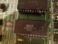
My edit rom is: 901474-C3. I think that bin might be for a 50hz display (based on the filename and also reading the link at 6502.org)
 
Last edited:
That's an 03 isn't it...

That means it is a 60 Hz ROM - which matches with your location.

I am going to suggest that you try and burn a compatible 2K EPROM with the image code I pointed you at earlier just to see if it will work. Do you have a blank EPROM and a means of programming the device?

Dave
 
Yup, I used it already on this project to make the pet tester rom. I still have a couple blank eproms.
EDIT: well I thought I did, but turns out only one was blank and my attempt to write to it failed so it's not blank anymore.
Time to pull out the UV eraser which works when it's in the mood.
 
Last edited:
Yes and no...

From my understanding it adjusts the framerate - it is not related to the mains frequency. However, from an ergonomic perspective, it is generally more acceptable to have the monitor framerate matching the mains frequency - although with the advent of high-frequency lighting these days I have my doubt whether this is now a factor or not.

I think the modified 50Hz image should be fine in your existing 60 Hz machine. Although that is a supposition at this point in time. Happy to be corrected by others...

Dave
 
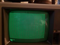
Hey now we're getting somewhere!


20230216_153819.jpg


The geometry is a little off but I think I can adjust that if I open up the back of the monitor and tweak some of the internal pots.
At first the v.hold was off but I was able to adjust that.

It does look quite a bit darker than other sources I've plugged into this monitor, this is with the contrast at max and the brightness as high as it goes before the black background starts to become just a green background.
Maybe some adjustment to the adapter? Maybe R9, the 75 ohm resistor just before the composite jack?
 
Simples :)...

Try tweaking the monitor geometry first. I have another idea if that doesn't work. There is a register setting that can tweak where the video line starts relative to the horizontal synch pulse.

Dave
 
Hey now we're getting somewhere!


View attachment 1253092


The geometry is a little off but I think I can adjust that if I open up the back of the monitor and tweak some of the internal pots.
At first the v.hold was off but I was able to adjust that.

It does look quite a bit darker than other sources I've plugged into this monitor, this is with the contrast at max and the brightness as high as it goes before the black background starts to become just a green background.
Maybe some adjustment to the adapter? Maybe R9, the 75 ohm resistor just before the composite jack?
If you like you can lower the series 75 Ohm resistor for more signal, try a 47 or 39 Ohm.

There are two magnetic rings on the back of the yoke and you can easily re-center the raster scan to the right. The displacement or angle between the two rings sets the field strength of the combined magnet, and rotating them both together rotates the field. You will find by trial and error the position that centers your image. The width looks ok, you might want to reduce the scan height, on the V height control.

(the thing that sets the H position of the data on the screen, with respect to the raster scan, is the leading edge of the H drive pulse with respect to the leading edge of the first character pixel, that is set by the PET circuit. In this case the leading edge of the H drive pulse generates the leading edge of the H sync pulse, so we cannot advance that in time with the current circuit,so as to make the data arrive relatively later so as to shift the data to the right on the screen. To do it electrically, the H sync pulse would have to appear , or be delayed, prior to the start of the leading edge of the H drive pulse, that can be done by delaying the H sync pulse just a little less than one whole scan line. Interestingly enough, the designers of the SOL-20 put a delay circuit in to create delays for the purpose of positioning the screen data on the raster scan. It would require another 4049 and a couple of preset pots to make vertical & horizontal position controls, so that could be a delux version of the adapter)
 
Last edited:
I do have more 4049's and some pots. I wouldn't mind doing some experimentation on a breadboard.

Since I have a few more of these adapters (pcbway's minimum quantity is 5) if you or anyone else watching this thread wants to have one to try out on other pets let me know I can send them out.

I'm curious how it works on a non-crtc pet.
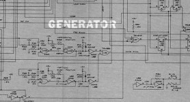
If you check out the SOL-20 schematic on the Deramp website you will see how to do it.

Actually, I stand corrected, the delay part of the circuit used a 4001, not the 4049. The two control pots are VRI and VR2. If you visit the Deramp website you will get a clearer copy of the schematic..
 

Attachments

  • DELAY.jpg
    DELAY.jpg
    143.9 KB · Views: 3
Hmm a 4001 I don't have.
Well I guess for now I'll try adjusting the monitor and then see if I can get the keyboard working properly. It's getting close to being a finished project thanks to all the help I've had on this forum!
I still need to clean off the rust and repaint the case, it's been an extremely mild winter so I might have a chance to take it outside and do that this weekend.
as for loading data I do have a datasette which I used to use on my c64, I think that should work on the pet as well? It needs some adjustment but I think I can get that going.
 
Back
Top