• Please review our updated Terms and Rules here

Neglected PET needing some love

Well done everyone for getting a viewable image on the monitor, however if the monitor is also used with other sources I think it would be better to shift the active screen area to the right by trying the hack which daver2 mentioned which can adjust the placing of the left edge of the active screen area relative to the sync pulse. That way you don't have to meddle with the monitor again when you go to use it with one of the other signal sources.
 
true. I did some adjusting today and was able to pull the image to the right by maxing out the h.hold. Then tested the monitor on two other sources: an apple //c and one of those battery powered plug & play tv games (I keep that around as a quick and dirty composite video source for testing)

Between using the PET and the other two I had to adjust the v.hold and v.size (both of which are accessible from the external pots) but after doing that the apple looked great and the tv game wasn't bad, it was off the screen a bit on both sides but it was like that before doing all of this.

Yes, if the H hold pot is adjusted the picture (data inside the raster scan timing) will shift left & right. But if that is used as a tool to do it, and it is displaced too far one way, sometimes when the set is switched on and off, the H osc won't re-capture.

In the TV industry the horizontal oscillator's control is called an AFC (automatic frequency control), but actually it is a typical PLL circuit. The H osc itself is set up to be a VCO and is controlled by a filtered error voltage that represents the difference in frequency of the H osc and the incoming H sync. The signal that represents the H osc, is often taken from a high voltage point in the Flyback area, fed back and filtered with an RC network and compared with the incoming H sync in a circuit with a pair of diodes. The diode output generates the error voltage stored on a capacitor, reminiscent of a sample hold circuit. In parallel with that capacitor is a series RC combination which is the "anti-hunt" network seen in most PLL circuits. It is the feedback pathway that can be altered to adjust the H position of the image, when the H osc is locked:

By altering a capacitor and or resistor in the PLL feedback loop leading to the diodes, which is difficult without the schematic (which is why I did not suggest it).

In some VDU's they added an independent control for this called the H. Phase control, I would doubt your Apple VDU has such a control, it was more common in color VDU's, but it might.

When it comes to finding the correct setting for the H hold control, it often baffles people because once in lock appears to remain in lock , once captured, over a large range of positions of the control. The way to adjust it and know 100% it is correct , is to disconnect the H sync feed or remove that from the composite signal, which is easily done if the composite signal is generated by the adapter, then set the H hold control so that the picture/ image is just barely floating by horizontally, then you have set the H osc's free run frequency to match the sync frequency.Then reconnect the H sync.

Probably on your VDU, by the look of it, you could reduce the scan width if you wanted to, it is an inductor in series with the yoke's H coil that has (normally) a ferrite slug. If you do it, only use a plastic tool, never metal or it can crack the slug.

Most TV's were set up by the manufacturer with moderate over-scan of the CRT face and therefore some of the raster edges not visible. Some computer VDU's though were set up with just a tad of overscan where the raster edges just overlapped the screen perimeter and others slightly under-scanned an not even reaching the CRT perimeter.
 
Last edited:
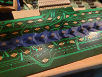
Well I've been experimenting with ways to get this keyboard going. What I've been trying recently is to take some rubber domes with conductive pads (new stock, unused) and tape them onto the PCB.
Then I have two choices, one is to leave the existing rubber nipples in the plunger and this cuts the key travel in half which isn't necessarily bad but a matter of personal preference I guess. The other is to take that nipple out and just let the plastic plunger push down on the dome which feels pretty much the same as before this "mod":

petKeyboardDomes.png

The good news: It's the best working solution I've come up with so far and it doesn't damage or modify the pet so if I do happen to come across those original nipples I can undo all of this. The bad news: It seems like I'm still having issues with some keys like I have to press hard or I get key repeats. Since the conductivity of the dome isn't the issue I can only assume it's due to damage to the contacts on the PCB itself. Some of the keys do look like the previous owner has very aggressively "cleaned" it as I see scratch marks on the pad and around it.

I wonder if there's a mechanical keyboard project for the pet, one specifically for this keyboard (business keyboard), not that I wouldn't mind switching keyboard types but that would probably involve burning another rom so I'm trying to keep it simple for now.

Edit: I actually did find a project: https://github.com/sjgray/CBM-MX-Keyboards/tree/master/B-V1-R1
but it would cost nearly $150 ($86 for PCB manufacture plus shipping) which I'm not going to do. Of course that gives you 5 PCBs so I'm wondering if someone out there has already gone this route and has 4 unused PCBs laying around.

I might be able to increase the conductivity of the pcb by flowing solder over the contacts.
 
Last edited:
There are lots of conductive rubber discs used for calculator repairs, one of many sizes & kits & types:


You could stick these onto the end of the original plungers and acquire the near full key travel.

I found these worked in the SOL-20 keyboard, even though it was designed for capacitive discs, but due to the design of the circuitry anything less than 68K would trigger it. However I used discs harvested from a Sun-4 keyboard, to keep it original.
Yeah I looked at those. I was thinking I need ones that are relatively the same diameter as the worn out ones I have and the set that has a variety of sizes would have too few of the size I need, and the other listing those pads are too large. But I guess now that I think about it I could use a hole punch to punch and just use the disc that was punched out. It seems that is pretty close to the right diameter.
 
Yeah I looked at those. I was thinking I need ones that are relatively the same diameter as the worn out ones I have and the set that has a variety of sizes would have too few of the size I need, and the other listing those pads are too large. But I guess now that I think about it I could use a hole punch to punch and just use the disc that was punched out. It seems that is pretty close to the right diameter.
Not sure what size you need but they come in 3mm:

 
Not sure what size you need but they come in 3mm:

Hmm yeah 3mm is the correct size. those don't look like 3mm in the image though
 
True.

The strange thing is when I have those original rubber pads which I painted with the conductive paint out on thr bench and I test them they work really well. Much better conductivity than a brand new carbon pad.

When I touch it to the pcb contact it registers the key press no problem.
but when I put it all together and close it up then the keyboard is really flaky; some keys I need to press repeatedly or hard and some repeat.

I'm wondering if it's the lumpy nature of the paint so I might try running each over some fine sandpaper to try to flatten the surface so it makes even contact with both halves of the contact on the pcb.

That might help with the conductive discs. But just a tip, never use abrasive paper on gold plated pcb tracks that are intended as switch contacts. The most abrasive paper you should apply is A4 printing paper, soaked with contact cleaner. The Gold is ultra thin, we are talking 10's of microns if that, sometimes just a few microns as a "flash" of gold. If you remove it, the copper underneath will show and it is much more reactive to atmospheric water and airborne compounds, it will oxidize later and give future troubles.

To clean the gold, just use a cue tip and some contact cleaner, like CRC's CO contact cleaner. That will get rid of the thin insulating film that builds up on gold over the years. I have talked about this many times before, related to things like DIP switches and gold touching contacts in the Attenuators of Tek scopes, how a transparent insulating film builds on gold surfaces over time.

In any case, once you have cleaned those Gold Fingers, it is then up to the the conductive pads. Did you get those 3mm ones I suggested ? If not I think you should get them now.

The touch tests you are doing are likely confounded by your body capacitance, which injects a burst of charge. When the keyboard is all assembled and isolated from outside influences, that is when you will see how well the particular conductive discs you are using work out.
 
Last edited:
There are a lot of tiny screws that hold the PCB to the rest of the keyboard. Check to make sure you are not missing some of them.
Does anyone have a photo that shows the location of the screws? As I recall they are scattered all over the board.
 
Yeah I think I did lose one. But the ones I have, half of them are rusty so I might just look for a new set of screws there.

Well I tried a little experiment, I cut off the carbon pad off of one of my rubber domes and glued it to the existing pad on the pet's nipple (okay I'm running out of words to describe all of these tiny components, but by nipple I mean the rubber piece that's original to the pet's keyboard and has a (worn out) carbon pad on the end of it). Anyway before doing this the rubber dome works fine I can place it on the PCB contact and press it and the key registers just fine but after gluing it onto the nipple (covering the worn out carbon pad), letting the glue dry, and trying that out, no contact at all.

I'm pretty sure I didn't get any glue on the surface of the pad and I can even measure the same resistance with a multi-meter (about 400 ohms) so I'm thinking the angle at which the pad hits the PCB contact is important because it needs to make even contact with both halves of the contact.

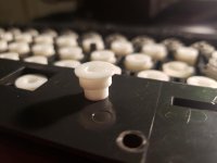
So I'm thinking this is going to be too fiddly and tedious for me so I started trying to think of other options. What I came up with is a way to use the rubber domes. If I take the nipple out of the plunger (the white plastic shaft that connects the keycap) then there's a cavity in there (where the nipple was), if I could design and 3d print a plug go in there with a small cavity in the end of that just the size for the rubber dome to go in, then all I have to do is carefully cut away the excess rubber on the dome that surrounds the carbon pad.

After about 7 iterations (getting the dimensions just right was a pain) I came up with something that works:
20230307_062752.jpg

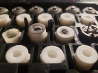
This snaps into the plunger and then the rubber dome goes into that:
20230307_062800.jpg
The one of the right is how they'll all be, I cut away the excess rubber so that the carbon pad can make good contact. I already tested that one and it works great I'm just waiting for a few more plugs to finish printing and to carve out enough free time today to do all that cutting.

-------------------------------------------------------------------------

I do have a keyboard related question: This pet uses the Business keyboard. Does it not have PETSCII characters, like the special graphics characters? I tried writing a little basic program like this:
10 for i=1 to 255
20 print chr$(i);
30 next i

However I didn't see any petscii characters, also it seemed to freeze up. I just don't know that much about the pet to know if this is expected or not.
 
They are all PETSCII characters...

It is just that the business keyboard has the upper case and lower case character set enabled by default.

There is a POKE that is required to switch the upper case and graphics character set in instead. I am not at home at the moment, so I will post the POKE later for you (unless someone does it in the meantime). There are plenty of posts at VCFED that do contain the POKE as well. It is also in the User Manual.

If your machine 'froze' that is not normal...

Dave
ah okay, well now that I have my keyboard working better I can play around with it some more and try to find the specific character it was trying to print when it froze.
 
okay it didn't freeze up, I can see the cursor is still flashing but I think what's happening is certain control characters are having different effects when I print them.
I can output 32-127 no problem, when I try to do 128-255 I see a bunch of petscii characters and other stuff, also a few beeps, and then for some reason the computer seems to go into like a 20 column mode or something.
if I do 1-31 then I get a few beeps and I'm stuck with a cursor flashing but I can't type anything.
I'm chocking this up to my ignorance of how the pet works.
 
Yes, some of the non-printable characters don't do what you think using this mechanism. They are special control codes to BASIC.

If you want to see the full character set, you have to POKE the characters directly into the video memory.

Dave
 
For graphics character set: poke 59468, 12
For text character set: poke 59468, 14
This will reset/set the 'Graphic' output signal from the VIA (UB15) to the upper address line (A10) on the character generator (UA3) to select the the desired character set.
 
Surprised you need to replace the contacts. I have just restored a completely dead keyboard by rubbing the carbon pads with paper.

But watching with interest, your replacement project.
 
Well the keyboard has gone from completely not working, to mostly not working, to (now) mostly working. It's still a little uncomfortable to type on though as there's enough key-presses that don't register unless I'm slamming the keys. It seems like it's due to the PCB now. On some of the worst keys I've been able to get them working well by adding a layer of solder on the contact but it's a little dangerous to do this as heating up the contact has (in a couple of cases) caused some damage. The "D" key almost got ruined, it looks pretty bad but surprisingly it survived and actually works pretty well.

But I don't want to continue with soldering as I'm worried I'll end up destroying a key's contact altogether. Obviously I've already tried cleaning the contacts and even used deoxit on each one. Every time I try something the keyboard gets a little closer to working perfectly but it's not quite there yet.

The mechanical keyboard option might be an option after-all. I sent an email to the guy who designed it because I noticed he had photos of a finished product so I assumed he would have had more than just one PCB created and he might be interested in selling me one of his extras. Well he got back to me, didn't want to deal with shipping internationally (he's in CA, I'm in US) but did let me know of another PCB manufacturer which is based in Canada and would have much lower shipping costs to me. Still, after all is said and done (including buying the key switches) it would run around $100. That's not terrible I guess if the end result is a perfectly working mechanical keyboard and if I could design & 3d print some kind of adapter that would let me use the existing PET keycaps on it that would possibly make it worth while.

I haven't decided to go this route though as it's still on the pricey side and I feel like I've got this keyboard 95% there. I suppose I could try to sell the other 4 mechanical keyboard PCBs to offset the cost but I don't know how much demand there'd be for them given they're for the PET business keyboard. Anyway for the moment I'm going to do nothing and just wait until I have another idea, something safe to try that might improve the contacts between the carbon pad and the PCB.

Like I said the 3 or 4 that I've soldered onto are working perfectly even a light tap and they register 100% of the time but I'm also running the risk of irreparably damaging some key contacts that way.
 
Back
Top