• Please review our updated Terms and Rules here

New to Apple II & Troubleshooting

Yep - post#87. Speaker works and is connected. I never hear a beep though occasionally hear some crackling from it.
 
Yep - post#87. Speaker works and is connected. I never hear a beep though occasionally hear some crackling from it.
I did see that when you posted but that wasn't sure if the conditions were the same since symptoms have changed since then. Have you performed the additional checks I suggested in post #95?
 
If I were troubleshooting this the first thing I would do is to:
  • Remove all DRAM chips in the second and third row and leave them out for all further testing.
This has been the case for ages. Only the first row of populated with known-good chips.

  • Remove all the ROMs except F8, check output pins (D0 - D7: pins 9, 10, 11, 13, 14, 15, 16, and 17 respectively), install F0 and repeat testing. Repeat installing the next and measuring until all ROMs are reinstalled.
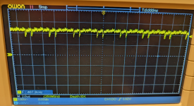
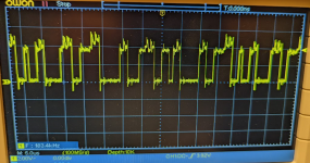
F8 has been the only ROM installed for ages. Again, this is inconsistent across power-ons. Sometimes it's a noisy high:

1646347208212.png

other times its chatty like what I think I'd expect to see.
1646347157438.png

This was the same behavior as I replaced each ROM. When one chip displayed the noisy high, they all did. Ditto the chatty pattern.

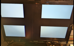
When I got to D0, the pattern changed to black cross on white background. Removed D0 and black cross remains. Multiple restarts always yield new black cross pattern! Remove the ROMs one by one and black cross remains.

1646347309739.png

So, physically the machine is back as it was 20 mins ago and I have a new pattern! A couple more restarts and I'm back to the flashing vertical bars.

All the ROMs back in and I'm still with flashing vertical bars.

When I had the black cross, the noisy high was less noisy.
  • Remove B6 and recheck the input pins on D0 - D3 (first four chips from the left)
Removed B6 (an LS257N) .... and which are D0-D3? My board coordinates start at A1?

  • Replace B6 and pull H11, measure signals. Since the 6502 talks to the data bus through H10 and H11 I am not sure what to expect.
Measure signals where?

cheers!
 
I have to go back and re-read what was going on when I made the recommendations. While in the process of doing so I was reminded of the odd behavior of the 6502s SYNC signal where it suddenly appeared to be working. Given the intermittent behavior you're now observing it might be worth it to keep an eye on this pin to see if there is activity on this pin. Perhaps connect the second channel of the scope and leave it there while other troubleshooting is taking place?

Also, it has been my experience on these older systems that a quick power off on cycle is insufficient for everything to reset. There have been cases where I've had to leave them off for approximately 30 seconds.

Finally, just to be certain you have measured the power supply voltages while it is powering the system?
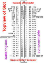
I have a few things to do this morning but will go back and re-read the context of my recommendations and get back to you.
 
Finally, just to be certain you have measured the power supply voltages while it is powering the system?
I took the readings at the PSU ages ago, but not while under load.

Revisiting this, I can't get my DMM probes into the back side of the power connector while it's connected so I used the expansion bus connectors to take readings.

Using this as a reference, I see correct voltages in the right places with the system powered up.

1646398655218.png

Interestingly (or maybe not), I get continuity between GND and pins 33 & 34 (not 50 or 25 though).
 
I took the readings at the PSU ages ago, but not while under load.

Revisiting this, I can't get my DMM probes into the back side of the power connector while it's connected so I used the expansion bus connectors to take readings.

Using this as a reference, I see correct voltages in the right places with the system powered up.

View attachment 1239111

Interestingly (or maybe not), I get continuity between GND and pins 33 & 34 (not 50 or 25 though).
I recall your having taken voltage readings at the start of this endeavor. However, as the symptoms mysteriously change I like to ensure previous readings remain accurate.

That's interesting about pins 33 and 34 so I tested continuity between ground and each pin. Pin 34 had consistent continuity however pin 33 only briefly had continuity when I first touched the meters probe. After about half a second resistance showed infinity.
 
Last edited:
Removed B6 (an LS257N) .... and which are D0-D3? My board coordinates start at A1?
Apologies as the way I wrote this statement is confusing. What I intended to have you do is measure data bits 0-3 and not chips located at a specific board location. Here is a (hopefully) non-confusing statement of what I intended:

Remove the chip located at board position B6 and recheck the input pins to the four DRAM chips located at board positions C3-C6 (first four chips from the left). These four chips represent data bits 0-3.

Measure signals where?
Again apologies for the confusion...measure the input pins to the same DRAM chips as I referenced above.
 
Hi all - haven't had time to update or work on the Apple2 recently.

I have a new symptom though - nothing at all on the display now!! TV says 'no signal'. Tested working with Acorn Electron composite output.

I'll pick it up again soon!
 
I'm back!!

I've armed myself with a T48 programmer, an LA1010 logic analyser and I'm revisiting the old Apple beastie! I've also been watching Ben Eaters excellent series on basic 6502 computers.

Update: Using the Logic chip test functionality of the T48, I found a couple of duff chips. A 74LS00 in A2 and a 74LS32 in C14. These have been replaced and I'm back at the flashing vertical bars. I've replaced the 555 with a new one. I know the 6502 itself works since I've put it in a Beeb and it fires up just fine. I've populated the lower 16Kb of RAM with 8x known good 4116s (tested on a DRAM tester).

There's a few chips I can't test with the T48 - 2x 8T28s bus transcievers, a 558 quad timer, and a 9334 latch thingy. I'll try work out ways to test them or just seek to replace them if I can easily source replacements.

The big outstanding thing I need to test is the 6x ROMs themselves. I can't get the T48 to read it. I've also lashed together a Raspberry Pi ROM reader and I don't get consistent results. I'm to understand the ROMs themselves are 2316 chips. The T48 doesn't have any setting for 2316 - closest being AM2716. The size (0x800) and D & A pin placement are the same however the CS logic is different. The datasheet for the 2316 says that pins 20 & 21 (CS1 & CS3) should be held low while pin 18 (CS2) should be high. Then I can read the ROM. So I've put the chip on a breadboard and tied the D&A, Vcc and GND lines back to the T48. However, I just get FFs back. I've tried every permutation of high/low on those CS pins to no avail.

So .. few questions for now...

1. What should I expect to see on an otherwise working Apple II Europlus with all the ROMs out?

2. What should I expect to see with just the leftmost ROM in place (F8)? I understand there's some monitor program?

3. Any thoughts on a definitive method to read those ROMs to verify if they're good or not?

Last time I had a go with the logic analyzer, I was getting inconsistent results. That was before I replaced the two busted 74xx chips. I'll have another go at it soon.. I was looking on the address lines of the 6502 to see if it was looking for the reset vector at least.

I think looking at the data lines of the F8 ROM chip at power-on should be a good thing to do also? That's one way of testing it I guess!

cheers all & happy new year!
 
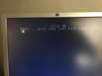
When the 6502 is not running the result is usually vertical white bars. If the 6502 is running but no code to execute (as in no roms) I think the result will be a screen full of ?? and @@ characters which represent uninitialized ram $00 and $FF because the rom code has not executed $FC58 to clear the screen. I do know what happens in a good II+ with only an F8 rom installed, you get this screenshotonly rom installed is good F8.jpg
 
Thanks... okay.. so vertical sort-of-flashing white bars on the screen... yet I'm seeing what I *think* I should be seeing when 'scoping the 6502. Chatter on all the normal lines etc.

Lower 16K RAM is in and I see what looks to be good RAS & CAS. I also see chatter on all Dout and A lines.

F8 ROM is in place and again, I seem to see what looks like normal chatter on the various lines.

So I had then had a look at the chargen ROM down the bottom. It seems quiet ... CS3, CS1 and CS2 sit H, L, L in that order and the address and outputs are all low. Maybe it hasn't kicked in yet? Maybe it's dead?

If I get time tomorrow, I'll put the logic analyzer on F8 and see what I see.
 
If you remove the chargen rom and power up do you get an all white screen ? That is what is normally seen if no char rom. But also you should get a couple speaker beeps behind the scene with only F8 rom and no chargen rom.
 
Hi - sorry .. been away a few days.

Pulled the chargen ROM and... flashing all white screen... flashes about twice per second. black/white/black/white....

No beep.
 
Last edited:
Seen this before.

In my case, the problem was resolved by swapping the ROMs out.


I spent much of this summer/fall restoring half a dozen Apple II motherboards.. In each case, the following approach seemed to work:

1) Find an equivalent board of the same revision that works.

2) For any bad board, remove all ICs, position the board vertically, and absolutely drench the board with DeOxit like you're spraypainting it, paying particularly close attention to flushing the DIP sockets when you do. All of it, multiple times---whatever you're not deoxidizing, you're essentially cleaning, dirt-wise. Allow it to drip-dry.

3) Do a systematic chip swap between the working board, and the non-working board, row by row... And do this in both directions; From working system to non-working, and vice versa. This is admittedly time consuming as hell, but, it's the best way to go if you lack a good chip tester at your disposal, or lack the time. If you dont have a chip puller, a small flathead screwdriver or Allen wrench wedged and pried between the underside of the IC and the socket bracing will work. Rock the chips out gently with a little wiggle--don't attempt to peel them up, else you risk bending pins.

4) Pull all ICs, toss them a jewelry cleaner with a little bit of warm water, a little dish soap and a few tablespoons of DeOxit. Let that shake and bake for a few hours.

5) Once everything's dried off, and all the legs are shiny-clean, give it another go. Reinsert everything in its proper place, in the proper orientiation, with the proper force.

6) If bootable, get a good tester application and ensure ROM checksums are good, and the RAM is still holding up.

I revived more than a few dead systems this way. I discovered over time that in the long run, it was actually more time- and cost-effective to go this route than it was to chase down rabbithole after rabbithole of theory after theory.
 
Last edited:
Back
Top