• Please review our updated Terms and Rules here

New, to me DEC PDP8E

Hi All;

Mike, Great Job !!!!!!
"" The car in the picture is my Model T. It's a 1926 TuDor. I found it in the north woods maybe a dozen years ago and restored it to nice shape. It's a driver not a show car. My son and I take it for a 1000+ mile tour each August. ""
I like it better when it is a daily Driver than a show Car.. I have almost had a 'T' A couple of times, It and a Deusenberg are my only wishing I could have aford type of vehicles..

Also, Would/could You make an attempt to Document what You are doing with the Switches and the PCB's, for those of us that would have no idea of not only where to start and what to do ?? As Your results are amazing..

THANK YOU Marty
 
Actually, most Model T people believe that a water pump actually impedes cooling. When I first got the car, the radiator was old and it would over heat due to poor heat transfer capabilities. I tried an water pump, because it was cheap. But it didn't help. A new radiator was the solution, although it cost $1000. Mike
 
Marty asked for comment on how I repair some of this stuff;

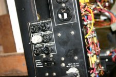
Cleaning the circuit boards is rather easy, I use isopropyl alcohol that I purchased from Walgreens. It's good because it will cut the oil and dirt and will evaporate. I have a variety of brushes, old artist brushes, tooth brushes and paint brushes. And paper towels. Nothing fancy. The front panel control board had some corrosion on it. It appears as green oxide. Copper and brass oxide is green. Here I used vinegar, which is a mild acid. Brush it on let it sit for a few minutes and wash it off with the alcohol. Depending on the amount of corrosion, you may have to do this a few times. You have to be careful and not let these liquids (especially the vinegar) get into parts like potentiometers. It could cause more trouble.

Once the board has been cleaned off, inspect the traces with a magnifying glass. Look closely at the corroded areas. Look for cracks and opens in the traces. Verify an open with an ohm meter. If you find an open, clean the trace and re-tin with solder. Then prepare a short piece of thin copper wire to fit over the open. Tin the wire and then lay it in place. hold it down with a pick and heat it with a solder iron until it is soldered in. Then recheck the trace for continuity. Again pretty simple.

My board had corrosion over 1/8 of the board and affected some of the parts. Some resistor and other part leads were broken off. These parts have to be removed. I use a de soldering braid to wick the solder away from the joint. First apply a little flux to the joint, then heat the joint and apply a little new solder to it. Then I flux the de soldering braid. Hold the braid on the solder joint and heat it with the iron. The braid will wick up some solder. When the braid is saturated, stop and cut that piece of braid off. Once most of the solder is off, try once more. This time place the braid one the part lead and CB hole, the push the iron into the braid so it contacts the lead and try's to enter the hole. This will wick most of the solder out of the hole. You can gently break (assuming the part is junk) the part and then pull on its leads and it will come out.

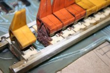
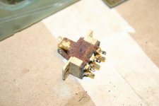
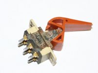
My front panel had two switches that were froze. The metal sides of the switches rusted, and this rust expanded into the switch and caused the switch slider to
IMG_0192.jpg
IMG_0239.jpg

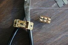
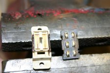
bind in place. First remove the switch with the method above. You can remove the switch lever by prying the metal sides apart, but it is not necessary, your choice. Then on each side of the switch the metal pieces have two expander that hold the bottom fiber contact plate. Gently compress each of these, then with a thin tool (razor blade), gently pry the finer bottom off. Once the bottom has been removed the slider and it's contacts can be removed. The contacts are loose so don't lose them. Now the switch is apart. I first soaked every thing except the fiber base and contacts in some soapy water with ammonia, scrubbed them and let them dry. The base contacts are cleaned with a brass brush and alcohol. I had to use a pick to get some of the crusty stuff off. The slider contacts and the metal sides of the switch are then soaked in vinegar to remove the corrosion. The contacts only for a few minutes. They then can be removed and buffed up. The sides of my switch were pretty badly corroded. I let them in the vinegar for a day or so. I would brush them and pick at the rust. You have to be careful here, if the switch is too rusty you may not be able to save it. Once you are satisfied with the cleanliness of the parts, re assemble them. Place the slider into the switch case
IMG_0244.jpg
IMG_0243.jpg

and the contacts in the slider. I used a little floor wax on the sides of the slider to aid in movement, but not too much. You don't want the wax to eventually get unto the contacts. Next place the fiber base back onto the switch case. If you try and bend the tabs back in place to hold the base onto the switch, they most likely will break off. So I just held the switch together with string and used a little JB weld to secure the base. Put the lever back on by bending the sides. Test your switch and then re-solder it back on to the CB.
IMG_0251.jpg

Hope this helps. Mike
 
Hi All;

Mike, "" Hope this helps. ""

YES !!!!!!!!!!!!!!!
It cleared some questions I had, I have done this in the past, but, have not always had good luck.. So, this helps..

THANK YOU Marty
 
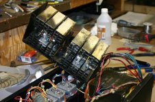
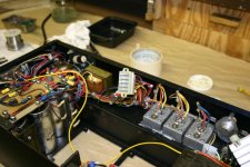
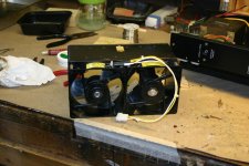
While I'm looking for replacement parts for the front panel control board, I've been looking at the power supply. I thought that the board were oil coated, but the the pass transistor cage is just loaded. The fans have a very heavy coat on oil, dirt and metal chips.

IMG_0279.jpg

So, I've transferred my attention to the power supply. I wanted to replace the power plugs and sockets J1-6, but now I will have to do a major clean up job on this power supply.

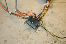
As I disassembled the transistor cage for cleaning, started to test the transistors and found one bad one. The large socket and plug connector is also in poor shape, loose and dirty.

IMG_0286.jpg

I also decided to clean and replace all the heat transfer stuff from the transistors and the power diodes. It was all dried out. It looks like a lot of time just cleaning coming up. Machine tools live in an dirty environment. Mike
 
While cleaning the fans, I noticed that they can not be original. One has a date on of 1986 and one from 1991. So the machine must have seem some maintenance. Even these fans have a boat load of congealed oil and dirt on them. One with so much that it would not turn. Mike
 
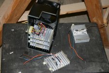
I'm just about done with the pass transistor cage. After removing a 1/2 pound of oily dirt from the case, heat sinks and wiring, I've started to reassemble it. I also decided to replace J7, which is the connector for the 5 pass transistor cells. The connector showed some signs of heating. The 6th cell is the heat sink for the diodes. Here I cleaned them up and replaced the heat sink compound as I did on the pass transistors.

IMG_0301.jpg
IMG_0300.jpg

I thought that I mention there is an easy way to remove the pass transistor cage, which I would have liked to know about prior to my doing it. I got it out, but some of the parts became loose and fell into difficult spots to recover. If you ever have to do this, Start by first removing the 8 screws on the outside that hold the fan guards in place. This will also release the entire cage. Next unplug J7 and remove the two red wires that come from the diode cell and go to the capacitor bank. The cage can now be pulled out, but the fan power wires will still be connected. I just cut them. Later I replaced them and added a plug to make the job easier next time.

IMG_0292.jpg

Making progress, Mike
 
The power supply in my 8/e failed last year. The LM723 +5V regulator failed, caused the +5V output to go high, tripped the crowbar circuit, and blew the +5V fuse. I had to solder lots of wires to the regulator board so I could get a 'scope on the signals. Once I could see what the regulator was doing it was not difficult to find the problem. I have been told by several experts that the +5V fuse holder was upgraded because the original version melted.
 
I had a fan failed in one of mine last year. There wasn't enough slack in the wiring to get the heat sink assembly out intact so I unclipped the diode part in situ to remove the pieces. After that I discovered that the fan itself was OK after all and one of the (quite thin) wires going to it had corroded through inside the insulation. It was a little awkward to get the assembly reassembled in situ, not much room.

I found that many of the bolts holding the bus bars which join the capacitor bank together we're quite loose. Likely a result of years of vibration. If you're still working on yours make sure they are tight as they are a key part of the smoothing circuit.
 
M, that is interesting In that my power supply also had the 5 volt fuse holder replaced. Probably had a similar problem.

IMG_0307.jpg

Bob, after working in a power plant for more than 40 years, I am familiar with loose sttuf caused by vibration. I have or will check all the hardware for tight,
Thanks Mike
 
That brings up another item I was thinking about. Are there card extenders for the omnibus or the power supply cards? Can they be found or do they have to be made? Thanks Mike
 
If you need some for the little PSU cards you might need to lash something up but you can certainly get an extender for the omnibus from a small company called Douglas Electronics here http://www.douglas.com/index.php/6-de-8.html . They're very easy to deal with and used to small orders. I can't remember the size and format of the PSU cards offhand but possibly they might be able to help there too even if you need to cut something down a little.

If you need to work on one of the cards which has the over-the-top connectors you might need some ribbon extenders so that you can mount 1 of the boards on an extender. I made some up by cutting a couple of the Douglas connectors down and wiring together with ribbon cable. Other folk have managed by tagging temporary wires to the boards and bringing them out to a scope probe.
 
Last edited:
That brings up another item I was thinking about. Are there card extenders for the omnibus or the power supply cards? Can they be found or do they have to be made? Thanks Mike
You may be able to find extenders, they existed. In the early 70's I did board repair on 8/e systems and we had a couple DEC-mfg extenders.

Just be careful you don't get the board plugged in backwards. It's possible with omnibus boards, and they tend to emit flames and smoke if you do. French-fried chips were a common problem with boards that were sent in to us by other techs from other sites.
 
I'm familiar with fireworks with badly connected items.

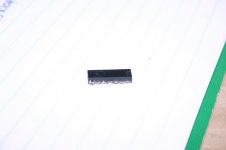
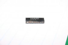
Get a load of this! I wanted to replace one of the corroded IC's on the front panel control board and it just broke off with a little handling. It was a 7416 and I have a replacement.

IMG_0309.jpg
IMG_0310.jpg

This one is an easy fix, but the chips next to it are DEC chips. One is a DEC 380 and the other is a DEC8881. After nosing around a little, I think that I can replace the DEC8881 a two input NAND open collector with a 7439 chip. The DEC380 is a little more difficult. It appears to be a two input NOR with an odd pin out. I figure I could use a 7402 and rewire the connection, but does anyone know of a direct replacement?

Thanks Mike
 
Many of the DEC-marked chips are Signetics tested to DEC's specification and branded for them. They mostly turn up on EBay from time to time. I've used all sorts and had no problems. The 380 is a bit of a nuisance as you say because of the pinout and I've rewired a couple of 7402s in the past. They do come up on EBay occasionally but less often. Also, one of the other posters on here (also from Scotland) has made up some tiny pcbs to do the pin-swapping. I've also used them but things can get tight if the boards need to go adjacent to suit over-the-top connectors.
 
Many of the DEC-marked chips are Signetics tested to DEC's specification and branded for them. They mostly turn up on EBay from time to time. I've used all sorts and had no problems. The 380 is a bit of a nuisance as you say because of the pinout and I've rewired a couple of 7402s in the past. They do come up on EBay occasionally but less often. Also, one of the other posters on here (also from Scotland) has made up some tiny pcbs to do the pin-swapping. I've also used them but things can get tight if the boards need to go adjacent to suit over-the-top connectors.


Hi Mike, that was me and I can let you have a few of the converter PCB,s if you like, PM me, however Bob is correct, it can get a bit tight. Look here

http://www.ebay.co.uk/itm/SP380N-IC...hash=item25655a0815:m:mn7WIc_IS3voKXJ5a1RTa1A

for the genuine thing.

Re the 8881, I have used a plain old 7401 in the past, not ideal as a bit light on the sink but unless you have a fully populated omnibus you should get away with it, or use 2 pigybacked .
BTW congrats on the 8 and the restoration work, nice one
Cheers
Dave
 
Last edited:
Back
Top