• Please review our updated Terms and Rules here

NOT WORKING CBM 3032

Desperado

Veteran Member
Joined
Nov 25, 2017
Messages
6,827
Hi guys, i am trying to repair this rusty Cbm of my friend!
I removed and washed main board and i measured voltges from power supply connector (J8):
I have 18 VAC between pin 1 and 5
and 2 VDC on pin 2 and 4.

Correct?
Thanks!
 

Attachments

  • Screenshot 2022-12-04 alle 15.37.22.png
    Screenshot 2022-12-04 alle 15.37.22.png
    843.2 KB · Views: 16
>>> rusty Cbm of my friend!

It looks much better than some I have seen...

What about measuring the AC voltage between J8 pins 8 and 9? There is a separate transformer winding for other voltages.

18 VAC sounds reasonable between J8 pins 1 and 5.

2 VDC on pins 2/4 doesn't sound correct though. How are you measuring this voltage? Where have you connected your multimeter negative (black) lead to?

Also, are these measurements with J8 plugged into the main logic board or disconnected from it?

Dave
 
2 VDC on pins 2/4 doesn't sound correct though. How are you measuring this voltage? Where have you connected your multimeter negative (black) lead to?
i connected black lead on pin3 of connector!
Also, are these measurements with J8 plugged into the main logic board or disconnected from it?
Disconnected!
What about measuring the AC voltage between J8 pins 8 and 9? There is a separate transformer winding for other voltages.
17,2 V
 
J8 pins 8 and 9 look OK.

I am surprised you measured anything at all between pin 3 and 2/4 with J8 disconnected to be honest!

The voltages on these pins are sourced from the logic board...

What you are probably measuring is the residual voltage stored on the terminals of the large external capacitor.

Don't forget to measure the AC voltage to the monitor either.

Dave
 
Ok seems that pettester is stucked on first page...and i can see some video noises on screen :(
 
First thing is to not worry about the noise and concentrate on the characters that are displayed.

Can you get a good photograph so we can see the characters that are displayed on the screen and then we can work out whether the video RAM is faulty and (if so) where... I can't tell that from the video on my phone...

Dave
 
So, that looks like video addresses $00 and $01 then $10 and $11 then $20 and $21 etc...

I have a meeting shortly, so let me think about that one.

Can you identify the schematic for the machine on the Zimmers website and I can take a look.

Dave
 
Just out of interest, what screen image do you get if you remove the 6502 CPU - and does the 'flickering' characters go away?

There is no CRTC device within this PET - so you should get the 'random' screen at power-up.

This should allow us to probe the video RAM and inputs to the video RAM address multiplexers with the oscilloscope.

For example, the video address multiplexers are on http://www.zimmers.net/anonftp/pub/cbm/schematics/computers/pet/2001N/320349-7.gif.

The signals identified as SAn go the video RAM address lines. The inputs to F3, F5 and F6 are the buffered address lines BAn (irrelevant if the CPU is removed) and the outputs from the counters G6, F4 and F2 that we are interested in.

Alternatively, as you state, you could go to the NOP generator and test the address lines and address buffers out followed by the address decoding.

You pays your money, you take your choice :)...

Dave
 
Last edited:
Ok, so I would go with the NOP generator next and test the buffered address lines (BAn) from B3 and C3 and the address decoder D2.

Dave
 
Ok, so I would go with the NOP generator next and test the buffered address lines (BAn) from B3 and C3 and the address decoder D2.

Dave
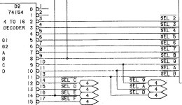
Ok i have waveform signal on every BAn lines of B3 and C3 (with Nop). With Nop inserted i see again some flickering chars :)
 
Pins 3 to 17 on D2?
 

Attachments

  • Screenshot 2022-12-06 alle 12.50.21.png
    Screenshot 2022-12-06 alle 12.50.21.png
    49.5 KB · Views: 4
Did you check for the correct frequencies and wave shapes on the BAn signals?

So the flickering is caused by READ accesses to the video RAM (as a minimum). That is what we now know.

I would check pins 1 to 17 (noting there is no pin 12 - this is GND).

Do you remember how to do this?

Dave
 
Back
Top