• Please review our updated Terms and Rules here

Notes for IBM 5110 keyboard replacement (pin out measurements)

Well, it seems all the modules that come with BT also include WiFi - and economically it's just cheaper to crank out the same chips in bulk? But agreed, the first thing I'll do is power off/disable that WiFi.

Although... if the device ends up embedded and closed up into the system, the WiFi might be a good way to do software updates remotely? For example, no (modern) keyboard is going to natively or cleanly support the APL inputs - and over time, I might come up with different ways to handle that.

Perhaps someday maybe I'll end up using a touchscreen as the keyboard? (or a keyboard with lots of little touchscreens, where I can have a mode and the key labels dynamically change into APL symbols) Imagine coding support for that without having to actually open up the vintage system.
 
I don't mind wifi at all. I think this keyboard adapter will be one of the more convenient ways to key in lengthy binary programs into 51(012)0 machines. Perhaps through this gizmo, my dream of IBM 5100 FORTH will be realised at last :)

The I/O you need to do is not fast at all, so if you wanted something simple, you could use a MOSFET logic level adaptor. It turns out that Sparkfun sells these on a breakout board. It's a bulky solution, and as it's a bidirectional adaptor, perhaps even overkill in a way (you only need one direction). But it should work: just pull the Arduino out of the circuit you made before, and plug the Pi in with this adaptor between the Pi pins and everything else.

Your other choices may work too, but I haven't examined them too closely; so would a +5V tolerant microcontroller.
 
I've tried the Arduino USB Host Shield 2.0, a couple times now. I'm sure it can work - but so far, no luck for me. Setting it up requires some soldering - which are quite small, but I think I did those correctly.

Uploading new software (to the Arduino) requires removing the USB Host Shield. I don't mind that so much (just it's kind of easy to bend pins by accident each time it is removed/inserted, so it's a bit of a hassle during the Development) -- but issue is: no keyboard is getting recognized.

All my USB keyboards have LED numLock, Caps, ScrollLock - hopefully that's not causing current draw across the USB port? But on the laptop, I'm not sure what current is going on the USB port as it is (if that even matters? it's a USB 3.0 port, but not sure if 2.1A, etc.).

I mention this because on the simplest USB keyboard that I have (no hub, no card reader), I noticed its 3 keypad LEDs flicker for a moment when first inserted (into the USB Host Shield), but then NumLock/etc LEDs don't come on thereafter when I press those keys that normally toggles those LED lights. They (the LED's) just blink for a moment when I first insert the keyboard into the USB Host Shield.


I'm just nervous that there are so many Arduino-like reference boards and USB Host Shield-like reference boards, there might be a QC issue in finding a pair of those that are built correctly (but then combined also with who-knows-what actual current on the USB port and keyboard internals). So, the repeatability of the build seems risky.


Hopefully one of the STM32's arrives soon, I agree it'll probably work out best.
 
STM32's I got didn't actually have BT. After adding a BT module, then I only have 9 GPIO pins left, and I need 10. Could probably work around that, but then I don't think the pins are 5v tolerant anyway. Could work around that also, but more parts/components to deal with.

So next I tried an ESP32. Will add a photo and exact specs later - but it does have BT (and WiFi). Setting up VScode (and ESP-IDF, target ESP32 USB BRIDGE) was new to me, but online tutorials did work - got the sample blink program working (have to remember to hold the tiny FLASH button when I issue a flash upload). Then I expanded the blink sample to test/verify which GPIO pins I could access from the code (i.e. set "PIN 0", use the o-scope to find which pin that was blinking, repeat for "PIN 1", "PIN 2", etc... i.e. didn't want to assume the labels on the board corresponded to the pin numbers used in this code library).

Next, I came across Guy Turcotte bt-keyboard on github... (last updated early 2022, so pretty fresh)

And, that worked "out of the box" ! In terms of: I was able to connect the BT keyboard, type stuff, and it shows up on the serial monitor connected to the ESP32. Cool, the device was receiving BT signals and relaying them back over the serial connections. Next step is then to merge the KBD5110 Arduino code, still working on that. But once done, it should mean: severe the serial IO, and can just use BT connection to command the 5110 keyboard. And this device can piggy-back on the A1 board pins, or be inline with the keyboard connector pins -- eitherway, the case can be shut and nobody need be aware it's there. Just charge up the BT keyboard, bring it near the 5110, and type your stuff. Now might need to find a BT keyboard that has programmable macro support!


Below is a summary of the changes to the Arduino original code, to adapt to this ESP32 ESP-IDF development environment. Ran out of time to actually run it yet, hopefully next weekend can do. I haven't yet figured out the UART/serial equivalent on the ESP32 -- it looks like it might be pre-configured where std::in and std_out are latched to the COM-port? Because in the "sdkconfig" file, it has these settings...

...
CONFIG_ESP_CONSOLE_UART_DEFAULT=y
# CONFIG_ESP_CONSOLE_UART_CUSTOM is not set
# CONFIG_ESP_CONSOLE_NONE is not set
CONFIG_ESP_CONSOLE_UART=y
CONFIG_ESP_CONSOLE_MULTIPLE_UART=y // <-- prob i should change to NO
CONFIG_ESP_CONSOLE_UART_NUM=0
CONFIG_ESP_CONSOLE_UART_BAUDRATE=115200 // <-- I noticed the FLASH speed is at something like 400K - 500K
(...not sure where PARITY NONE and STOP BIT 1 is set... maybe it's implied defaults)


Also, still not 100% sure if this ESP32 is 5v pin tolerant? But I did order 3 of them just in case I burn one out. (with the USB tethered in, I've seen a few 3.3V pins on power up, but not yet a 5v pin -- and I haven't yet tried applying 5v to the Vin pin; that's probably the next thing to try, unplug the USB, stick 5v on Vin and see what happens by probing each of the pins)


And for this code, not sure if there is something I'm overlooking in regards to pullup/pulldown defaults on the board? (in contrast to any Arduino defaults)

Code:
Draft of changes to adapt the KDB5110 from Arduino sketch to STM32 C code...

//                verified     ESP32 board label            Arduino pin#
#define PIN_KBD_P       21  // D21                          2

#define PIN_KBD_7       19  // D19                          3
#define PIN_KBD_6       18  // D18                          4
#define PIN_KBD_5       5   // D5                           5
#define PIN_KBD_4       17  // TX2                          6
#define PIN_KBD_3       16  // RX2                          7
#define PIN_KBD_2       4   // D4                           8
#define PIN_KBD_1       2   // D2    (tied to blue LED)     9
#define PIN_KBD_0       15  // D15                          10

#define PIN_KBD_STROBE  0   // D0                           11

// NOTE: If need more pins, or different pins, then there is also GPIO D25,D26,D27,D14,D12,D13 on the other side of the board. (for example, if using the blue LED pin ends up causing an issue)

MAIN:

    // INIT/SETUP
    gpio_reset_pin(PIN_KBD_P);                         // (probably not needed, but seemed appropriate)
    (same for PIN 0 to 7, and STROBE pin)

    gpio_set_direction(PIN_KBD_P, GPIO_MODE_INPUT);    // Arduino:  pinMode(PIN_KBD_P, INPUT);
    (same for PIN 0 to 7, and STROBE pin)

    gpio_set_level(PIN_KBD_P, LOW);                    // Arduino:  digitalWrite(PIN_KBD_P, LOW);
    (same for PIN 0 to 7, and STROBE pin)

    while (1)  // LOOP
    {

      out_parity = FALSE;  // assume EVEN parity

...logic to check inputs and decide GPIO state of bits 0-7
   (Arduino code used serial IO; STM32 will use BT... but will figure out the STM32's equivalent to serial IO to duplicate for testing)

      if ODD parity, set out_parity = TRUE

      if a valid IBM5110_kbd_code_was_decided {

        if (out_parity == FALSE)            gpio_set_direction(PIN_KBD_P, GPIO_MODE_OUTPUT);
        (...etc for PIN 0-7...)

        gpio_set_direction(PIN_KBD_STROBE, GPIO_MODE_OUTPUT);  // trigger ON  the STROBE for the scancode being pressed
        vTaskDelay(10);  // part of freertos/task.h            // Arduino:    delay(10);
        gpio_set_direction(PIN_KBD_STROBE, GPIO_MODE_INPUT);   // trigger OFF the STROBE

        if (out_parity == FALSE)            gpio_set_direction(PIN_KBD_P, GPIO_MODE_INPUT);
        (...etc for PIN 0-7...)

      }

    }
 
Last edited:
Mission accomplished! Finally got a few hours to combine the Bluetooth capability of the ESP32 and my original Arduino kbd-translation code, and can now connect a wireless BT keyboard up to the IBM 5110 (the IBM 5100 will be no different, just a different set of keyboard code translations -- I'll plug in a table for that soon).

The code is in github:

And is based on the ESP32 BT connection code by Guy Turcotte:

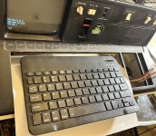
Here's the cheap-o BT keyboard I used for testing. The code to handle the GPIO pull-up stuff is essentially the same as it was on the Arduino Nano (different calls, but same idea) - and fortunately, the ESP32 is 5v tolerant :)

One minor issue is, I can't re-upload firmware to the ESP32 while the IBM5110 is connected and powered on (I have to turn off the 5110; I didn't unplug each cable to see which one was causing the conflict). I don't recall that being the case on the Nano. Not a huge deal, just an observation. The ESP32 dev kit came with some "FreeROS" that handles the serial connection and delay timing, and using VS Code as the front end. A little wild how it all "just works" (after adding the ESP32 target).

IMG_3609 - Copy.JPG


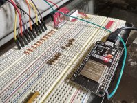
Same resistor (330ohm) setup as with the Arduino. I still haven't self-powered the ESP32 from the 5v out of the 5110's keyboard harness, but the idea is to package this up into a small container that would sit inside the 5110's case (although I don't have a 3d printer at the moment). No more wear and tear on the original keyboard -- and, now to find a BT keyboard with macro support, and then place your favorite demo program into those macros. One tiny difference -- the ESP32 and whatever C-library it is using defaulted ENTER to ASCII 10, whereas the Arduino stuff defaulted ENTER to ASCII 13. There is probably some config file for that (except it might involve re-compiling their standard C library stuff), so the kbd-translation code is adjusted to translate either value over into the IBM's EXECUTE scan code.

IMG_3605 - Copy.JPG

No idea how strong or reliable the signal will be once it's inside an enclosed case, TBD!
 
Last edited:
Nice work, but my problem is with BT keyboards in general--they tend to be cheap and terrible. Ideally, you'd want to interface a higher-quality keyboard. I never could feel comfortable typing on a notebook keyboard.

That being said, I'm embarrassed to admit that I have several IBM iPoint keyboards on various bits of equipment here. Keyboard resembles an older ThinkPad in terms of appearance and feel. Heck, when surplus, you could get them for $3 each NOS.

I expect that to change. I could purchase NOS Model Ms back in 1990 or so for $10 each on the surplus market.
 
Totally agree, the cheap BT keyboards are terrible, and the thin size leaves no room for any decent battery - but good enough for dev proof of concept. An Android phone can act as a BT keyboard.
 
Back
Top