• Please review our updated Terms and Rules here

Olivetti M24 - No POST

ChrisCwmbran

Experienced Member
Joined
Oct 11, 2011
Messages
483
Location
Cwmbran, Wales, United Kingdom
Hi guys,

Need some advice. My Olivetti M24 has been connected to the mains power and it's monitor today for the first time in many years. Doing the testing, the machine is fitted with it's HDD controller card, but the cradle with the HDD and FDD are removed (and obiously disconnected).

When powered on the machine flashes it's keyboard LEDs for a few seconds and then beeps but produces no display at all. The monitor is the monochrome M24 monitor. The two dials on the monitor are both turned fully clockwise as the manual says.

Interestingly, pressing control+alt+del does seem to cause it to reboot.

Ideas please? Thanks in anticipation!
 
If it's just one beep that means it booted successfully, is looking for a boot device and the monitor is likely the problem.
 
I know someone on here (Chuck(G)?? I think) has posted details of how to connect a 6300 to a VGA monitor but I can't find the posting anywhere.

Sadly whilst I've done tonnes of stuff inside PCs I've always shied away from monitors.

Any advice on how to diagnose this fault would be appeciated.

Does anyone have a pinout for the graphics card of the M24 please?
 
You're right again. :) Guess we'll have to wait till Chuck finds this thread.

The main problem with the message search feature is that if you indicate a member's post to search for it only returns threads in which that member was the OP. That feature really sucks when you're trying to locate a post from someone who wasn't the OP in the thread, like you're probably trying to do now.
 
Chuck's been at the dentist. He found the thread.

For a quick check on a VGA (LCD works fine) monitor, build this cable. I just whacked the D-sub connector and cable from an old VGA CRT monitor that was headed for recycling and soldered a DB25M connector to the end.

In my case, I could open the M24 mono monitor up and see the filament of the CRT glowing, so I knew that it was getting power. A pass over the CRT PCB turned up a cold solder joint.

However, many people wanted to fit an EGA or VGA card (8 bit) to the 6300/M24, so they disabled the video adapter. You can't remove it as it ties the motherboard to the bus converter, so one way was to pull one or two PAL chips (look for empty sockets on the video board). Fortunately, with the help of some folks here I was able to reverse-engineer the content of one of them and my machine is now happily belching video using the onboard video.

I'm going to assume that if your video board is intact, the motherboard video switches are probably set right. But it wouldn't hurt to check them.
 
Thanks for the advice so far.

I'm a little confused. Reading the AT&T PC 6300 service manual, it appears I have a P4 Display Controller Board, and they talk about a plug being substituted for the 74LS00 chip in position 6H and show a 14 pin DIL chip with strapping between certain pins to disable the onboard video. The chip in that position on my card is a 20 pin DIL chip, and has a label reading PL68 on it.

To further confuse, the settings for DIPSW-0 and DIPSW-1 appear to be for ROMs prior to 1.21 or those version 1.43 onwards. My BIOS chips are labeled as version 1.36! Typical of me to have the odd version that fits neither!!!
 
The service manual is really talking about a P2 kit, as far as I can tell. I have the same P4 board that you do and PL68 is the correct chip for that location. There was a 20 pin plug offered that shunted some of the lines to Vcc or gnd that disabled the board. But you could just as easily pull the PL68 and ignore the shunt on the P4 board. Alternatively, you could change a couple of jumpers.

Make up the VGA adapter cable and see if you get anything. You're going to like having color anyway.

I've got the 1.43 BIOS and some board upgrades as well.
 
The board is the display board, P2 is a old revision, P4 seems to be the most common. I myself have 2 PC-6300's and both have the P4 revision board.

I would also check to see if the monitor is getting voltage. With a multi meter (or a DC voltage reader) and check the voltages from the wires running to the display board. The orange and grey at P7 is 14v I believe, and if that has no power reading at all then the monitor won't be receiving power.
 
I'd love to upgrade my machine to 1.43 but having just bought an oscilloscope for working on my old computers, I don't have the funds for an eprom burner at the moment. What are these board upgrades you talk about?

There are some cuts and jumpers to traces, a new keyboard controller piggyback, etc. I don't know if they're worth the effort, however.

Service manual says +15 on the connector. But I'd still build the VGA cable--it's very simple.
 
Last edited:
Try a different VGA monitor. Mine works fine with an older 22" ASUS LCD--some newer ones don't have the low res range. I didn't change the jumpering from that indicated in the serivice manual.

At least you know that you've got video.
 
Ok my head hurts now. I've spent all day tinkering with this annoying little connector, and got no where.

I decided to do it using one of these http://www.maplin.co.uk/9-way-d-type-to-25-wayd-type-box-1670

And to do the connections within it using Solid Core Wire (1/0.6) - this may be a mistake (I'm reatively new to soldering and stuff) but it's a bugger to work with such inflexible wire in such a small space. The connectors have what they call solder cups for each wire to go into and they were very fiddly too.

Because Im confused about which side of the connector each image is showing it's hard to be 100% sure I've done it right!

I'm trying to unstress a bit before having another look - but at the moment it's very hard to tell if my adapter is wrong, or the video card of the machine is defective. I had until now assumed that because of the single short beep that the machine at least thinks its video card does work!!
 
Many, if not all, solder-cup connectors have, on one side of the connector or the other, pin numbers molded into the surrounding plastic. However, if you're looking at a DB25 male connector at the solder-cup side (not the pin side) with the 13-pin side on top, the rightmost pin is pin 1; the leftmost, pin 13. The numbers on the second row start again at the right with 14, and continue to 25 on the left.

For the three-row DE-15HD VGA male connector, the pins are numbered similarly with pin 1 the rightmost top row position on the solder-cup side and runs to the left at pin 5. The middle row goes from pin 6 on the right to pin 10 on the left. Finally, the bottom row is pin 11-15 in the same manner.

This might help for the VGA side

And This diagram identifies the signal names at the M24 connector.
 
Thanks for the advice Chuck. We made an adapter and double and trebble checked the connections for correctness and continuity.

I connected it to an AOC LM720A monitor (http://www.discoazul.com/tft-17-aoc-lm720a_en.html) which supports 640x350@70Hz, 740x400@70Hz, 640x480@60/75Hz, 800x600@60/75Hz, 1024x768@60/70/75Hz, 1280x1024@60/75Hz resolutions.

Nothing is displayed.

If I were to use my oscilloscope to check the red, green, blue, h sync and v sync outputs on the M24, which appear to be the only ones used, what should I expect to see? I presume I'm going to see 5v ish pk to pk signals, and one of the syncs to be about 60hz.
 
Last edited:
I'd have to go back to mine, but I think the horizontal sync will be about 32KHz. Chances are, if you see both horizontal and vertical sync, you'd probably see video also.

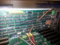
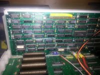
Do you know what revision of the video card that you have? Are there any empty sockets or sockets filled with jumper blocks instead of ICs? (Both those approaches were often used to disable the video controller so that a different one (e.g. VGA or EGA) could be used.
 
IMG_20120712_182854.jpgIMG_20120712_182903.jpg

It appears to be a P4 revision.

I was checking the dipswitches on the motherboard, and as I mentioned earlier in the thread it is a little bit odd. The motherboard has dipswitch tables for bios upto version 1.21 and for bios 1.43 onwards. My bios is a version 1.36 according to the stickers which isn't covered by either table. The monitor type is determined by two individual switches, so we tried all four options.
 
Sounds like you're perhaps past this already but have you tried a multisync capable monitor? Your input not supported generally means it does see the voltage but can't display that resolution or hertz range.
 
Back
Top