• Please review our updated Terms and Rules here

Osborne 1(b) Problem

ChrisCwmbran

Experienced Member
Joined
Oct 11, 2011
Messages
483
Location
Cwmbran, Wales, United Kingdom
Hi guys,

I have a problem with my Osborne 1b. When powered on it only displays a partial version of the initial screen:
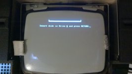
WP_20140826_15_45_45_Pro.jpg

When I press the RETURN key (with no floppy disk in the drive) the screen fills with "BOOT ERROR" messages but from the odd movements on the screen it appears to me that perhaps one of the 74LS series counter chips do with the screen isn't operating correctly however I don't know how to tell which.

Here is a video which might help:


I pressed RESET and RETURN again approximately 20 seconds into the video.

Thanks for taking the time to read this. Any help would be greatly appreciated.
 
Per our earlier discussion in the VCF IRC Chat... I have a copy of one of the technical manuals that include schematics. I'll look it over before trying to find out if I need a 1B updated.

I looked over the Xerox 820's video schematics during lunch, expecting a lot of similarities (hopefully a lot of improvements).

I haven't looked at the video so I'm missing that diagnostic information.

Looking at the two still images I thought it might be good to test to see if the keyboard is sticking or otherwise misbehaving to scroll the display or ignore user input... rule that out first before getting into the guts of the video circuit.
 
I was reading the tech manual and it says the sign-on message that displays "INSERT DISK" at that point will accept a Control-D to run diagnostics...

It says: "Single density versions of the Osborne 1 prior to the 1.3 ROM and BIOS include a set of built-in diagnostics which are accessible pressing ^D (control-D) when the sign-on message is displayed."

That might not help as I recall you mentioning getting a new ROM set.

It would have been dumb for them to have removed basic system diagnostics because when things go wrong, you can't access disk resident diagnostics -- its worth trying it anyway to see if someone ignored their boss and left them inside the ROMs. :S
 
I saw two mentions in the tech manual stating that was only prior to 1.3 so I wouldn't bother.

I'm reading to whole manual to learn all about the O1... they did some strange things... but usually that was to work around expensive components of the day. They do a dual-port of their dynamic RAM which makes sense so the Video Generator could use 4K for its character screen (32x128 virtual page but 32x24 scrolling video portal).

Curious that the keyboard has no power or electronics in its attachment. Its effective a switch matrix and the connecting cable powers rows and scans for key closures. Rather smart in that it simplifies the module and reduces cost in the keyboard attachment. That means you could disconnect the keyboard and use an multi-meter to detect a stuck switch (ruled out in this case); good to know.

I noticed that their floppy interface is customized; they replaced the FDD's control card with their own... i.e. you can just plug any 5 1/4" drive to their 34 pin cable... connector pins are redefined... don't know yet if they have any serious conflicts with standard drives. It would be nice to know if its feasible to make an UNDO to the modification that allows normal 5 1/4inch drives to be connected; I'll look at that later.

The three banks of memory is rather odd; that the floppies can't load directly into lowest 16KB of memory... is not great... it has to copy to high memory and then back in bank 0 copy that back down to the lower 16KB. Reverse to relay to write to disk from the 16KB block.

It may be that to make replacement FDD electronic boards, instead of matching a model's outline specifically for replacement...
perhaps instead a tiny SMT card with I/O would just be glued onto and existing board and all the connectors transferred to this little SMT board.

Other models just mean a different firmware loaded for that particular drive and maybe the connectors.
Maybe a simple cable translation card to match the connections of that drive to a ribbon the to SMT board.

That might carry floppies further into the future.
 
Last edited:
Your first screen image looks like the screen is scrolled to the bottom of the 128 character wide by 32 line *virtual* screen. It appears to show your screen has shifted down 8 lines to display lines 9-32 instead of 1-24. That suggests a problem in the display parallel interface adapter (PIA) chip that is set by the Z80 firmware to control the screen position. The chip may be dead or some of the chips that work off that data. You might try re-seating that PIA chip if its socketed (there may be another on the IEEE-488 interface) but its probably better to wait for subsequent tests.

Do this test first:
See if you can use the keyboard scroll move to go left and right, up and down. If that doesn't work at all or partially, the problem is localized to that circuitry around the PIA. Post a message here with the results of your scroll test.

Here's a similar sign-on message off an Osborne 2 Executive. You can see that your screen image has the first 8 lines rolled up and off the screen.
http://www.vintage-computer.com/images/osborneexecutivecustomlogin.jpg

I'll post the chip ID and whether its socketed later.
 
Last edited:
Your PIA (UC15) chip is not functioning, or at least not initializing.

As the PIA also controls the floppy disk drive TWO SELECT pins (which I believe was your original problem was floppy drive related), this seems to encompass all the problems you've experienced in one failure.

If you test the control the scroll video scroll up/down/left/right, I'd bet that it won't work normally. If it does work than the PIA is only failing to be initialized. I think your display is stuck at the left margin and at the bottom of the 32 lines of the virtual page. It may be offset one line and one character column if the PIA outputs are read as FFh and the counter increments the value back to 00h quickly.

I think the rest of the screen scrolling circuitry is working fine downstream from the PIA as it must be working in order to render the screen as you see it. Therefore the problems is the PIA or upstream from it like a chip enable problem. I'm betting on the PIA being bad... if its socketed, perhaps re-seating it the chip in the socket will make the problem go away. Be careful if you're not familiar with reseating chips in sockets, someone can walk you through that if you've never done it before.

Operational information on this part of the circuit:
That PIA (parallel interface adapter) loads 3 important values, the starting character (column) address 0-127 (7 bits), the starting line number (row) address 0-31 (5 bits) and finally the two floppy disk drive select lines going to an open-collector buffer and then out the floppy cable. All three seem to have troubles, thus indicating the PIA.

The PIA column and row values are loaded into counters at the beginning of a raster line, the column and row address is used to access inside DRAM F000-FFFF (reserved for the video display ram) to fetch the bit pattern for a character which is loaded into a shift register and shifted out as video pixels.

The drive select pins if also never loaded or initialized means you can't select drives properly and by default selects both or none. So floppies can't be read until the PIA issue is resolved.
 
Back
Top