• Please review our updated Terms and Rules here

PDP-12 Power supply question

gnupublic

Experienced Member
Joined
Jan 23, 2019
Messages
198
Location
Germany, Berlin
Hello,
I'm beginning to work on my PDP-12 #580, starting with the power supply. I formed the capacitors checked all diodes. Then finally I started it. Most of the voltages came up, just missing 10V. The 50W 10V zenerdiode was defect.
I replaced this with a "super zener" build from an TL431 driving an Darlington transistor. I managed this to fit it using the plugs at the cooler. So it can be replaced easy if I can get this original zenerdiode.

5V was exact 5.06V and I tried to put some load on it. When switchen the power supply on and off sometimes the crowbar rises. Awfully this does not bring the circuit braker to open (without further load), so the 0.1 Ohm resistor got very hot and burned the board a little bit.
Later, with some load of 50 or 100W the circuit breaker opend, if the crowbar rises.
I read some similar problems of power supplys from 8/L and I will try to find out what I can do to avoid a voltage peak when switching on.

When I switched on with 150W of load, one time the crowbar rises and now the transistors are faulty. Both 2N4398 are defect.

I did not expext to be able to kill them, because of the circuit breaker, expected this to limit the current. The 2n4398 can do 200W or 30A (50A peak). So I expected to be able to drive more than 30A with both transistors.

But I cannot find any current values in the documents, can anybody point me to? The power supply named 724 maybe similar to the H724 of the 8/e. There I find 5V @20A (100W). Is this plausible for a PDP-12 also?
 
I wish I had something to offer here, but I'm not really an EE and power supply construction is way outside my wheelhouse. I assume there are schematics online for the PSU? If not, I may have some here I could scan. Otherwise, I will learn along with you and wish you good luck!
 
There is more information on 724 power supply in the G824 FlipChip schematic.

I made an LTspice simulation of the +5V part of the 724 power supply. You can fiddle with the load and components to see how the crowbar works.
 
The shematics of the 724 in "Maintenance Volume III shematics" does not contain any current/load information.
Also G824 shematics do not have any load or current information.


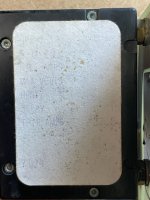
IMG_6568.jpg

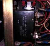
The circuit breaker has a sticker on it. But I cannot read anything. I beg there is a "TRIP AMPS 37" maybe?
Very unshure.
 
The Computer History Museum has corporate records from DEC, including 102763465 724 power supply 1974. May Al could look at that document and see if it has any additional information.
 
Hello Vince,
this is the one on the G824? Or is it the main switch/automat?
Sorry, it's the main power breaker on the back panel.

I remember the G842 as a bit of a bear to get in and out. I should have taken pictures when I had the G842 out (I actually did, but not of the sides of the breaker, and I of course don't remember if anything was written there.)

Vince
 
I have no experience with this power supply but I did go through a couple of adventures with circuit breakers.

Bottom line - they can't really be trusted to protect a delicate electronic piece of equipment from damaging itself.

They are thermal, and as such are slow to respond around the limit current, and inaccurate, with wide variation of the trip point depending on the ambient temperature. Easily derated by 30%. Some are even designed to respond slowly after they're powered, for applications where startup current is expected to be always much larger than working current.

Plus - yours are old and way beyond their designed service life for sure.

So - better to assume they're not there than trust them to protect anything.

-Alon.
 
Hello Alon,
thanks for sharing your experience. At the moment I'm only interested in the value of the circuit breaker, because there is no other information of the current or load of the 5V.
Meanwhile I'm pretty sure that the TRIP AMPS is 37.5A on the sticker.
I looked very close with different lights and me and the whole family comes to the same number. So I think that the if the power supply works at 30A (150W) for some times, it should be OK.
If then, for any reason, the crowbar triggers, it might be that the current gets too high, the circuit breaker too slow - and the transistors blow (silicon fuse). Hopefully not.
 
If then, for any reason, the crowbar triggers, it might be that the current gets too high, the circuit breaker too slow - and the transistors blow (silicon fuse). Hopefully not.
The only reason the crowbar circuit should trip is an overvoltage on the +5. I looked at this a couple of years ago when Vince was trying to bring his machine to life. From memory it should crowbar at about 6.5 volts. Vince had all loads disconnected and the supply would transient above this point on startup and trip every time. Needless to say, this is hard on the pass transistors. TTL is quite tolerant of overvoltage with most of that era devices not self destructing at up to 7.5 volts. At least not for a while. TTL will eventually overheat and not operate well at those voltages, but they don't die instantly from it either. I am pretty sure that this power supply needs a load on it or the crowbar will trip every time power is brought up. It depends on the capacitance found on the flipchip modules to slow the voltage rise. The load will of course depend on the options installed.

The crowbar should be able to apply a lot of current and the breaker should open in a reasonable amount of time. When the crowbar trips at 6.5 volts the circuit could be pulling in the range of 60 amps which should open the breaker. When the crowbar activates you can ignore all the other loads as the output voltage should drop to under a volt. My guess is that the breaker probably should be replaced but that the pass transistors were probably degraded as well. You should also check that 0.1 ohm resistor and make certain that it is 0.1 ohms in circuit. I have seen examples of ancient resistors where the leads are plated and there is significant resistance between the leads and the soldered connection on the circuit board. A couple of ohms resistance here would reduce the current to the point where it would not be sufficient. It is also possible the SCR has degraded but since it is never supposed to conduct, your testing might be the first time since the factory floor where it was triggered. A bad SCR is unlikely.

Under normal operation the breaker and crowbar circuit do nothing and don't need to be there. They are present for the situation where a pass transistor shorts which is a common failure mode.

The G824 is easy to test. Put +8 volts on pin 2 of P1. Put a lab supply set to a little below +5 volts on pin 1 of P2. Connect the GND on the board to both negatives. Watch pin 3 of P1. It is the base drive for the pass transistors. It will change as you move the 5 volts up and down. You can slowly turn up the 5 volts and see at what point the crowbar triggers. You can current limit the supplies to a few hundred ma.

Best Wishes on getting it running!
 
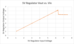
I did a check on the PSU in my PDP-12 and the problem is the same as in the PDP-8/L. It doesn’t regulate well when the input voltage to the regulator is close to 5V. The output goes well beyound 5V, up to around 6V until it starts regulate properly when the input is above 7V if I recall correctly. So in the startup phase I can imagine that this feature together with low capacitance will cause it to trip the crowbar.
 
I did a check on the PSU in my PDP-12 and the problem is the same as in the PDP-8/L. It doesn’t regulate well when the input voltage to the regulator is close to 5V. The output goes well beyound 5V, up to around 6V until it starts regulate properly when the input is above 7V if I recall correctly.
Exactly. I confirmed the same thing in my 8/L:
1675950551648.png
@Roland documented this behavior and designed an add-on OVP circuit for the 8/L, which I built but haven't yet installed, but it was the motivation for me to characterize Vin vs Vout of the 5 volt regulator.
So in the startup phase I can imagine that this feature together with low capacitance will cause it to trip the crowbar.
Maybe a slight modification to either the regulator or the OVP would be helpful to prevent the annoying OVP trip events.
 
Thanks for all the hints! And thanks Mattis for your work on the 8/L. The circuit of the G841 is little different from the 8/L, but it's more easy to separate the crowbar from the voltage regulator.
Schematic here
There are two Zener diodes, one for the voltage regulator and one for the crowbar.
Changing the crowbar Zener diode brings the crowbar voltage down. I think 4.7 is OK, crowbar then shuts around 5.9V.

For the overshoot I tried to change some things in the feedback of the difference amplifier, but with no good result.
Than I simply put a capacitor 10uF ( C4) parallel to the original Zener diode. It now takes obout 4ms for the voltage to raise 5V. No overvoltage at all. I do not find any dates for the SDA-7 transistor, so I'm not quite shure of this could be a problem in any case. With my laboratory power supply it works fine.
 
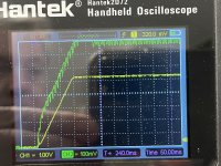
It took a while to fix this in the power supply, but today I think I got it.
The green curve is the input voltage. The yellow curve is the output.
In this case with a load of 22A into 5V.
I had to increase the capacitor C4 to 220uF. With lower values it did not work.

Now the crowbar is not triggerd any more. But I had to remove the old burned resistor....

Greetings,
Volker


1678016863526.jpeg
 
It took a while to fix this in the power supply, but today I think I got it.

I had to increase the capacitor C4 to 220uF. With lower values it did not work.

Now the crowbar is not triggerd any more. But I had to remove the old burned resistor....

So, I'm curious... was the fix to swap only C4 with a 220uF part?
Or did you also make the changes described by @MattisLind ?

quote from post #15: https://forum.vcfed.org/index.php?threads/pdp-12-power-supply-question.1241847/post-1299917
"I wrote about my mods to the regulator board more than five years ago in this thread. I think it should be applicable to the PDP-12 as well."
https://forum.vcfed.org/index.php?threads/pdp-8-l-restoration-psu-problems.59694/
 
In the meantime, I'd really recommend putting in some safety fuses in line with the factory breaker. It's 50 years old at this point and I would not count on it to protect anymore. Maybe as an on-off switch.

The 8/L's have fuses in them, and yes they are worth replacing.
 
Back
Top