• Please review our updated Terms and Rules here

PDP-8/a parts needed

It's also possible that the 32Kx8 QC problem was batch-specific and you got "lucky" with your tubes :-{.
I do have tubes from different batches, according to the markings on the chips, as I hoped initially it was a bad batch. In the original Lafferty design, there were differences in how often they would fail, but none of them worked. The Cypress branded chips I had used before were fine, as were the few other brands I had on hand.

I haven't attempted a rigourous check of the Alliance batches, though I do have IIRC three pair that I was doing the debug with. None of those seemed to work appreciably differently once the timing/shoot-through issues were cleaned up.

Vince
 
I received the system today. While I was looking at the PDP-8/a Minicomputer handbook I noticed that even when using the KK8E CPU board set in an 8/A chassis no M8320 Bus Loads/Terminator board is required? Am I missing something or is the bus termination handled in the chassis itself?

The system came with a 5 board Kearney & Trecker CNC control board set and a Kearney & Trecker SA-4004 hard disk controller.
 
the KK8E CPU board set in an 8/A chassis no M8320 Bus Loads/Terminator board is required?
The KK8E board set consists of M8330, M8300, M8310 and the M8320 bus loads/terminator. All DEC configured 8A/n20 systems included the M8320. Maybe yours went missing somewhere along the way? The KK8A (M8315) design has the terminators included on the module.

re: your sig - "M8317 (4 port serial board)"? A M8317 is the PDP-8/A combo memory extender, bootstrap & powerfail option. I presume you're wanting the the KL8A M8319 PDP-8/A 4 channel serial I/O?
 
I received the system today. While I was looking at the PDP-8/a Minicomputer handbook I noticed that even when using the KK8E CPU board set in an 8/A chassis no M8320 Bus Loads/Terminator board is required? Am I missing something or is the bus termination handled in the chassis itself?

You are missing something. The M8320 card goes in slot 1 (Top of the chassis). The M8320 is the bus termination and provides the pullups for the open collector drivers on all the other cards. The KK8E CPU cannot work without the M8320.

With the M8315 KK8A CPU you cannot have the M8320 as the pullups are done on the M8315.

I found the reference to this in the PDP-8A Operators Handbook at the bottom of page 3-2 and in the dedicated Omnibus Slots table 3-2 found on page 3-3.

There is a resistor (R55) that must be removed from the M8320 for use in the 8/a. I've not looked into why that part needs to be removed.
 
I just checked and the M8320 that came out of my 8A-620 chassis is missing the resistor at R55 and the other 3 M8320's all have them.

On the drawings for the M8320 R55 is a 470 ohm with one end connected to test point pin AA1. This was probably used in test. It is not clear why they would need to disconnect this on an 8/a and not on the 8/e. But a modified board should still work on an 8/e chassis.
 
The KK8E board set consists of M8330, M8300, M8310 and the M8320 bus loads/terminator. All DEC configured 8A/n20 systems included the M8320. Maybe yours went missing somewhere along the way? The KK8A (M8315) design has the terminators included on the module.
I did not get the M8320 with the CPU board set (I was more interested in getting the KK8E/EAE matched board set) but I have a spare so I should be ok. I will remove R55.
re: your sig - "M8317 (4 port serial board)"? A M8317 is the PDP-8/A combo memory extender, bootstrap & powerfail option. I presume you're wanting the the KL8A M8319 PDP-8/A 4 channel serial I/O?
Thank you, I corrected this in my signature.

My 8/A is a 620 so I don't think it's M8417 CMOS memory ready (there is no slot for the regulator board).
 
You are missing something. The M8320 card goes in slot 1 (Top of the chassis). The M8320 is the bus termination and provides the pullups for the open collector drivers on all the other cards. The KK8E CPU cannot work without the M8320.

With the M8315 KK8A CPU you cannot have the M8320 as the pullups are done on the M8315.

I found the reference to this in the PDP-8A Operators Handbook at the bottom of page 3-2 and in the dedicated Omnibus Slots table 3-2 found on page 3-3.

There is a resistor (R55) that must be removed from the M8320 for use in the 8/a. I've not looked into why that part needs to be removed.
Thank you for your help. I found the reference and where to put the boards.

What would be the recommended slots for the and MM8AB 16K core board that I have coming.

Slot​
Board​
1​
M8320 Bus Loads
2​
M8316 Options 1
3​
M8317 Options 2
4​
5​
6​
7​
8​
9​
10​
11​
12​
13​
14​
15​
16​
M8300 – CPU Registers
17​
M8310 – CPU Control
18​
M8341 – EAE
19​
M8340 – EAE
20​
M8330 – Timing Board


Also, the PDP-8/a Operators Manual mentions an G8018 power board to power core memory. Do I need one and if so what slot should it go in?

Should I avoid the hex wide slots when adding additional boards?
 
"What would be the recommended slots for the and MM8AB 16K core board...?
Should I avoid the hex wide slots when adding additional boards?"

No, those hex wide slots (5 connectors) are there to allow support for memory above 32K. Your MM8AB should be installed in one of the 5-connector slots. The KT8A MMU should also be in a 5-connector slot.

The G8018 PSU/regulator is the expected power supply for 8A core memory systems. What power supply came with the box you have?
 
Put the 16k core in slots 4, 5. If you get another one at some point put it in 6, and 7. The MMU is on the M8317 board. You disable that part if you have the 128k version of it.

The G8018 is the normal power supply found in the 8/a. In the 12 slot chassis the power supply is accessed from the front. In the 20 slot chassis there are two of the G8018 accessed from behind a cover plate at the rear of the chassis. They use bayonet type fasteners to hold on the rear cover and to hold the G8018 in place. If you remove them be careful as the clearance is limited and you will bump stuff that you don't want to bump. There are no guide slots so they tend to drop once the edge connector comes out of the backplane. And they are fiddly when you put them back in. The bayonet fasteners are also not really rugged and on all of my 8/a's some of them don't lock into place correctly.

Vince has one of the nicest looking 20 slot chassis I have seen. His even has a cover over the fan wiring on the left side. I didn't know there was such a thing.

I took so long to write this I see there is a new note that answers some of this.
 
"What would be the recommended slots for the and MM8AB 16K core board...?
Should I avoid the hex wide slots when adding additional boards?"

No, those hex wide slots (5 connectors) are there to allow support for memory above 32K. Your MM8AB should be installed in one of the 5-connector slots. The KT8A MMU should also be in a 5-connector slot.

The G8018 PSU/regulator is the expected power supply for 8A core memory systems. What power supply came with the box you have?
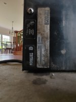
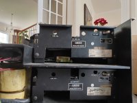
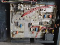
It looks like I have two G8018's. See the pics below.
 

Attachments

  • 20220520_113955_HDR.jpg
    20220520_113955_HDR.jpg
    789 KB · Views: 7
  • 20220520_114020_HDR.jpg
    20220520_114020_HDR.jpg
    832.8 KB · Views: 7
  • 20220520_113858.jpg
    20220520_113858.jpg
    1.5 MB · Views: 7
Put the 16k core in slots 4, 5. If you get another one at some point put it in 6, and 7. The MMU is on the M8317 board. You disable that part if you have the 128k version of it.

The G8018 is the normal power supply found in the 8/a. In the 12 slot chassis the power supply is accessed from the front. In the 20 slot chassis there are two of the G8018 accessed from behind a cover plate at the rear of the chassis. They use bayonet type fasteners to hold on the rear cover and to hold the G8018 in place. If you remove them be careful as the clearance is limited and you will bump stuff that you don't want to bump. There are no guide slots so they tend to drop once the edge connector comes out of the backplane. And they are fiddly when you put them back in. The bayonet fasteners are also not really rugged and on all of my 8/a's some of them don't lock into place correctly.

Vince has one of the nicest looking 20 slot chassis I have seen. His even has a cover over the fan wiring on the left side. I didn't know there was such a thing.

I took so long to write this I see there is a new note that answers some of this.
Thank you.
 
Here is a strange question.

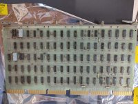
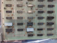
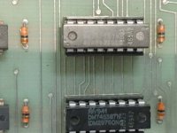
The PDP-8/A documentation says that the M8316 Option 1 and M8317 Option 2 boards should be in quad slots (2 and 3 to be specific). However, the M8317 (revision 5010935D-P2) board that I have has signals on the extra edge connectors.

This board does not match the board in the 1976 PDP-8/A Minicomputer Operators manual either. The date code on the chips is 1979 & 1980.

What am I missing?
 

Attachments

  • 20220520_171335_HDR.jpg
    20220520_171335_HDR.jpg
    1.3 MB · Views: 6
  • 20220520_171343_HDR.jpg
    20220520_171343_HDR.jpg
    1.2 MB · Views: 7
  • 20220520_171352_HDR.jpg
    20220520_171352_HDR.jpg
    388.3 KB · Views: 6
The older 158A2/159A2 ROMs booted PTR, RK8E, RX8E, RF08/DF32, or TA8E.

Looks like you have the 465A2/469A2 boot ROMs, which can boot PTR, RK8E, RX8E, or RL8A. The switch settings are the same for the first three, and the RL8A settings are like the TA8E.

Vince
 
Vince,

Do you mean TD8E or TA8E (I'm not familiar with TA8E).

Also, the M8317 Board has signals on the 6th edge connector. My case only has 5 connectors for the wide slots. Why are there signals on an unused edge connector, do you know what they are for?

Thanks for all of your help,

Mike
 
I believe the 6th edge connector was only used for testing at the factory. The 5th connector is used to select which 32k dram card was selected for the 128k memory configuration. I should probably look but there might also have been an additional voltage provided on the 5th connector.
 
I believe the 6th edge connector was only used for testing at the factory.
I see on the print sets that there are a ton of test points on connector F. Almost every signal at the right edge of sheet 3!

Good question Mike -- I hadn't noticed those before.

Vince
 
I believe the 6th edge connector was only used for testing at the factory. The 5th connector is used to select which 32k dram card was selected for the 128k memory configuration. I should probably look but there might also have been an additional voltage provided on the 5th connector.
That would make sense because the M8317 does not have any signals on the 5 connector.

The 16K Core board, however, does have signals on the 5th connector.

So, the Hex wide memory boards use the 5th (E) connector for the additional addressing lines that are driven by the M8416 (which would also need to be in a "HEX" slot). That is why the M8417 is recommended for slot 2 or 3. It doesn't drive the extra address lines so it doesn't need the slot.

Vince and Doug, thank you both.

Now all I need to do is clean everything and put it together and get it to boot.

Any Idea why the Roland/Vince bootloader board does not work in a PDP-8/A?

Thanks again,

Mike
 
I haven't looked into why Roland's design doesn't work in the 8/a. It might work with the KK8E CPU.

There is a major difference between the KK8A and KK8E in that the KK8A drives the bus with tristate bus transceivers instead of open collector drivers. The timing is slightly different to ensure that the bus transceivers go tristate before anyone else might pull a signal to ground and cause a shoot thru event.. The KK8A also can only drive one chassis, up to 20 slots. You are not supposed to chain chassis together when using the M8315.

I do know that the front panel work slightly differently on the 8/a. It could have something to do with that. It could be something really simple like the boot button on the front panel generates a short pulse that Roland's board does not see but the M8317 does. I am just listing the things I would look at. I really don't know.
 
Back
Top