• Please review our updated Terms and Rules here

PET 2001-8C glitches when screen is redrawn/cleared...

e5frog

Member
Joined
Dec 29, 2015
Messages
33
Location
Sweden
... and also upon pressing enter when entering a line of program in BASIC.

Looks like this when running Fire!
https://www.youtube.com/watch?v=Ey8gmapT_3I

It's small horizontal lines in a diagonal kind of pattern, appears on every screen update in the clip as far as I can see, quite annoying.

Any tip on what to check or swap? All regulators seem to behave, didn't see any spikes with the oscilloscope.


Also a bit annoyed by the little bright spot that appears slightly to the right of the middle about 5-6s after PET is shut down, but I saw someone somewhere mention swapping some cap to solve that. Apart from a home made 013 ROM replacement and a broken 6550 I'm pretty much pleased with the current functionality. Need to straighten out the case in a few places, it seems to have gotten a lot of punishment - this is quite tough metal sheet.
 
I think the original 2001 PETs had 'snow' especially when assembly language games wrote to screen without regard to video blanking for faster animation. CPU writing to screen only during blanking was a crutch used in the 2001-8 PETs to keep snow to a minimum. If it was bypassed with a special POKE/Store instruction to the VIA chip, the screen would scroll faster, etc but there would be snow.

This problem was cured in next generation PETs with faster video RAM that allowed refreshing video on the opposite phase of system clock as the CPU access.

This is related to the 'Killer POKE' issue whereby BASIC programs written for original PETs to bypass blanking and later used in PETs with the 6545 CRT Controller, might have a problem.

See http://www.6502.org/users/andre/petindex/poke/index.html for more info.
 
It could be an explanation, this program is written in BASIC though and no POKE to 59458 can be found in this listing, so no "blanking bypass" has intentionally been added.
ftp://www.zimmers.net/pub/cbm/pet/games/english/fire.prg

Funny thing: it's in English, unless you get too close to the fire with the chopper - then it says "sie haben feuer gefangen" - "you have caught fire" in German! ;-)

However, it could be writing to video RAM that causes this, is it supposed to be like this on the PET 2001-8C, so there's no chance of animating anything on screen without getting these glitches ("snow")?

http://www.6502.org/users/andre/petindex/poke/index.html#history
When the video logic wants to read byte of video data when the CPU accesses the video RAM, it reads invalid data. This results in "snow" on the screen.

So even when not doing anything with the killer poke, there's still this kind of snow - on all old PETs?

http://www.zimmers.net/cbmpics/cbm/PETx/petfaq.html
The old PETs were slow because the print character ROM routine
waited for the interval between screen scans before updating the screen
memory. This reduced conflicts over the screen RAM which would have resulted
in random pixels (snow) being illuminated on the screen. There was an input
on one of the I/O chips which was hooked up to the video circuitry and told
the routine when to access the video RAM.

So this means there shouldn't be any snow then... so the "I/O chip" (the VIA I guess) could perhaps not be functioning properly, or something else in that circuit?
 
Last edited:
A Swedish collegue mentioned that it doesn't look like the regular "snow" mentioned.
 
However, it could be writing to video RAM that causes this, is it supposed to be like this on the PET 2001-8C, so there's no chance of animating anything on screen without getting these glitches ("snow")?

Write a simple program that does a 'do nothing' FOR-NEXT loop and see it if causes noise. If not, write another FOR-NEXT loop that prints to the screen enough to cause scrolling. Does this cause snow? If the blanking circuit is working correctly there should not be a lot of snow. Use this program again with the blanking bypass POKE and try again. You should see snow. Reset the PET after this test.
 
A Swedish collegue mentioned that it doesn't look like the regular "snow" mentioned.

I only have a 8032 PET. I do not remember what the snow looks like. If there is snow whenever you input from the keyboard or print to screen, there may be a hardware issue with the video controller circuit (which is complicated) :( or maybe just bad Video RAM. Do you have a scope?
-Dave
 
I've got a bit more glitching.

I see the display updating faster after the POKE, but not much snow. Perhaps the Labyrinth pattern is masking it. Anyway if your snow is different and I notice that it contains mostly horizontal dashes, it may be caused by a different hardware problem. Do you have an extra video RAM (6550) to try a piggyback test?
 
Last edited:
I tried the POKE59458,62, it was hard to notice any difference in game but I got new occasional interference at the prompt asking to play again, almost a character long showing here and there.

I have tried swapping video ram for a new pair before (same as plain ram), didn't notice any difference. What would a piggyback do?

Yes, seems some other hardware might be causing it, don't know where to start looking.


A simple for-loop doesn't affect the screen at all.
Printing a single letter 10000 times doesn't cause anything visible.

Pressing enter after entering the program-line causes "snow" if the number of characters in the listing is more than 10, the longer the row the more flicker.

Double characters repeated, no snow, nothing with four characters, nothing with 8 chars

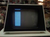
When looping a write with 9 characters I get an empty area from the third line of what builds the T I'm using to print, one full line of characters and the top bar of the next row of T:s. When program stops the screen returns to normal. The empty spot is not a camera-effect.
IMG_20160103_010932.jpg
 
Changing to ten characters the tenth character isn't showing on the lowest row, no longer any empty area.
Eleven characters and the last two chars aren't showing.
Printing twelve, 13, 14, 15, 16, 17, 18 not more than first nine visible characters on the last row.
19 chars, only the last one is gone.
Don't know if this is normal behaviour so I'll stop there.

Printing a full row of characters in a loop, covering the whole screen doesn't cause any snow like interference like in the Fire-program.
 
Last edited:
I have tried swapping video ram for a new pair before (same as plain ram), didn't notice any difference. What would a piggyback do?

No need to piggyback if you already tried swapping RAM chips. Piggybacking by placing a new chip on top of soldered chip allows looking for a change without having to remove the soldered chip. If a change is seen, that implies chip is bad and should be replaced.

It is starting very much to look like there is an issue with the video controller logic (see sheet 3 of your board type). This is the most complicated part of the PET and will require the use of a scope or logic analyzer. When you finish with this troubleshooting you will be quite an expert on the PET design. The last time this took about 50 messages but we found the problem. Are you willing to try? If you have the old 32008 board with the 6540 and 6550 memory chips, the schematic is http://zimmers.net/anonftp/pub/cbm/schematics/computers/pet/2001/320008-3.gif
-Dave
 
Fixed a Fairchild Channel F with a piggyback solution once, had lost most of the color and tried piggybacking a few logic chips in the area of the RF modulator - found the right one and problem was solved.

Yes, lets get to the core, the video controller logic, I downloaded the sheet(s) earlier, also spent some time with the video board layout that had the PCB pattern mirrored compared to the components. Yes, it's the 6540, 6550 320008 board.

I'm willing, oscilloscope and cheap 8 channel logic probes ready... also a selection of various logic chips.

Thanks for wanting to help out.
 
I'm willing, oscilloscope and cheap 8 channel logic probes ready... also a selection of various logic chips.

That's all you really need, but comparing signals to a working system makes things much easier. Do you happen to have access to another 2001 PET? If not, we can start by looking at the timing of the four states of the control sequencer. The two Q outputs of the B6 flip flops (top center of schematic) determine the states as shown on the schematic in the diagram to the left of the flip flops.
 
No extra machine, this is my first PET.

So, shall I measure with the startup screen or while running the game that shows the repeated interference?
Both Q outputs as well as VERT DRIVE and VIDEO ON signals on the logic probe?
 
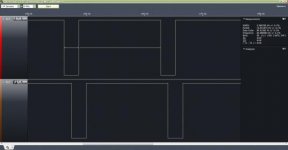
Measured at 8MHz (with the Saleae copy) Q outputs of B6 flip flop, if probing from startup I get some life on pin 5 but it then stays at high while pin 3 bursts four 0.5µs peaks 1.28ms apart (end to start), between the last of these four bursts and the first of the next four there's 12.8ms.

This is just the startup screen with the flashing cursor.

Really wish I had those little clamps now to put on IC pins...


EDIT:
I tried finding something easier to check for interference than loading "Fire". With just this:
0PRINT"{clr}"
1PRINT"H":RUN
I get two double dots moving a little back and forth in the lower left corner, like a row was taken from the H and thrown out twice. Changing to other characters sometimes change the position and the SHIFT+C character horizontal line produces a glitchy pattern of three lines in the lower right corner. Looks like fourth bar shows now and then. Other horizontal lines I tried produces no visible glitches.
 
Last edited:
Measured at 8MHz (with the Saleae copy) Q outputs of B6 flip flop, if probing from startup I get some life on pin 5 but it then stays at high while pin 3 bursts four 0.5µs peaks 1.28ms apart (end to start), between the last of these four bursts and the first of the next four there's 12.8ms.

This is just the startup screen with the flashing cursor.

Really wish I had those little clamps now to put on IC pins...


EDIT:
I tried finding something easier to check for interference than loading "Fire". With just this:
0PRINT"{clr}"
1PRINT"H":RUN
I get two double dots moving a little back and forth in the lower left corner, like a row was taken from the H and thrown out twice. Changing to other characters sometimes change the position and the SHIFT+C character horizontal line produces a glitchy pattern of three lines in the lower right corner. Looks like fourth bar shows now and then. Other horizontal lines I tried produces no visible glitches.

Very good troubleshooting. Let me think about screen issues. The signals we will be looking at right now are periodic and independent of what's on the display so it does not matter when you capture the data. Later we may have to look at the video data path. State 00 should like the Vertical Sync signal. For the State signals use 2V per division and 2 milliSec per division on logic analyzer.

The Saleae I have has wire wrap 'push on' terminations on the flying leads. If that's what you have you might consider getting DIP Clips like the link below. Make sure you get part number 923690-14 and 923690-16 or equivalent that have 'headless heads' rather than 'nail heads' or the test leads will not slip on. Nail heads are for test leads with 'grabbers' to help keep them from slipping off.

These 3M clips are available from Digi-Key
 
I looked around but couldn't really find any settings for the logic probe, more expensive versions have settings for hi/low levels... With the equipment I have - 8Mhz sample rate is the highest I can go. Two milliseconds per division? That's about 500Hz... ?
So the data I collected, is it strange in any way? I was surprised to see pin 5 stay high. Is the logic table referring to the two Q outputs?

I have one of those 3M clips, couldn't find it right now, would have been really nice.
Will make another attempt at finding it...
 
Never mind the measurements, I measured on the wrong side of the chip... Measuring 12 instead of 3 and 10 instead of 5, will check again...
 
Now measuring the proper pins (with logic probe) with the GND cable steadily attached this time.

They're both the same signal but the pulse train from pin5 is about 1.3ms (half a pulse width) after, 60Hz negative pulse, pulse width about 2.56ms.

So in 1.28ms divisions logic looks like this:
pin3: 001111111111100111...
pin5: 1001111111111100111...

Image4.jpg

Attachment seem to be shrunken, no way to see the full image?
Clicking this enough will reveal full image, it can be clicked a second time after it has opened.
 
Last edited:
This looks fine. State 00 is the time when both Q outputs are low. This all looks good. The frequency of the signals is 60 Hz. I thought European PETs might be 50 Hz but apparently not for the original 2001-8 PETs. So far so good! We now know that the main countdown circuit is working to specification and feedback signals to the sequencer control seem to be working.

The screen information you gave should give us clues for next test. Your description is good, but is it possible to get a video of screen posted when it is misbehaving?
 
Back
Top