Good detective work.
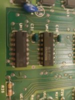
C31 is a decoupling capacitor. If it is getting hot it is faulty. It would be dragging one of the voltage rails down. Remember what I said about your senses - sight, sound, smell and touch?
I assume you replaced buffers E9 and E10?
Going back, I assume you now get consistent pulses on CPU pin 7?
What are you now getting on the pins of UD2?
Remember, we have a procedure to follow... Is the CPU executing instructions (CPU pin 7 pulsing) and does the operation of the signals on UD2 indicate that the PETTESTER ROM is executing correctly?
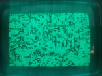
I suspect things are working correctly (that is where the letters are coming from) but we need confirmation of this by measurement.
I suspect we are now having problems with the video RAM, video RAM buffers or video RAM address multiplexers. This will be where we go next.
Dave