- VCF South West - June 14 - 16, Davidson-Gundy Alumni Center at University of Texas at Dallas
- VCF West - Aug 2 - 3, Computer History Museum, Mountain View, CA
- VCF Midwest - Sept 7 - 8 2024, Schaumburg, IL
- VCF SoCal - Mid February 2025, Location TBD, Southern CA
- VCF East - April 2025, Infoage Museum, Wall NJ
-
Please review our updated Terms and Rules here
You are using an out of date browser. It may not display this or other websites correctly.
You should upgrade or use an alternative browser.
You should upgrade or use an alternative browser.
Pet 2001N horizontal line
- Thread starter Desperado
- Start date
daver2
10k Member
So the problem is from UD6 pin 22 to UD7 pin 22...
Use your eyes to find out where the track break is...
It is unlikely to be a bad solder joint as the PCB tracking should be continuous. The solder joint should only be there to attach the IC socket pin to the PCB track itself. However, the track could be broken in the socket hole itself and a bad solder joint could be causing the problem then. This is one reason NOT to replace IC sockets and/or ICs UNTIL you know what the problem itself is...
Dave
Desperado
Veteran Member
- Joined
- Nov 25, 2017
- Messages
- 6,827

daver2
10k Member
You have the board - I don't...
If your multimeter tells you there is no connection between UD6/19 and UD7/19 and UD6/22 and UD7/22 then there is something wrong...
The track may be OK - but is the track itself actually connected to the oval pad that you solder the socket to?
The word "seem" is the key word. They can't be connected... Look harder I am afraid...
Dave
daver2
10k Member
Yes, the UD6 pin 19 oval solder pad appears to not be shiny and bright where the track exits to UD7. Is there actually any copper there - and is it physically connected to the track that goes to UD7?
Dave
Dave
Desperado
Veteran Member
- Joined
- Nov 25, 2017
- Messages
- 6,827
What can i do do repair this Dave?Yes, the UD6 pin 19 oval solder pad appears to not be shiny and bright where the track exits to UD7. Is there actually any copper there - and is it physically connected to the track that goes to UD7?
Dave
daver2
10k Member
Solder a piece of wire between pin 22 of UD6 and UD7 underneath the board once you have mounted two new sockets.
Ditto for pin 19 (and any other pins that have no connection).
Please (however) test ALL of the pins for conductivity between UD6 and UD7 NOW whilst the sockets are removed.
All pins should be wired between the sockets (apart for pin 20 which is the /CS pin) - i.e. UD6 pin 1 to UD7 pin 1, UD6 pin 2 to UD7 pin 2 and so on down to UD6 pin 24 to UD7 pin 24.
Look especially close at the oval pads that are not bright and shiny but are dull and tarnished.
Dave
Desperado
Veteran Member
- Joined
- Nov 25, 2017
- Messages
- 6,827
Ok thanks so much!Solder a piece of wire between pin 22 of UD6 and UD7 underneath the board once you have mounted two new sockets.
Ditto for pin 19 (and any other pins that have no connection).
Please (however) test ALL of the pins for conductivity between UD6 and UD7 NOW whilst the sockets are removed.
All pins should be wired between the sockets (apart for pin 20 which is the /CS pin) - i.e. UD6 pin 1 to UD7 pin 1, UD6 pin 2 to UD7 pin 2 and so on down to UD6 pin 24 to UD7 pin 24.
Look especially close at the oval pads that are not bright and shiny but dull and tarnished.
Dave
OldPETGuy
Member
daver2
10k Member
I think that is a PCB 'via' on pin 3 (address line 5) that goes to a PCB track on the solder side of the PCB and off to somewhere else.
Dave
Dave
daver2
10k Member
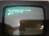
Excellent.
What have you now got plugged into the PET in terms of E9/E10, VIA, PIAs and BASIC ROMs?
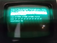
I am guessing you have buffers E9 and E10 in (otherwise the VDU test would fail, and so would Page 0 and 1 RAM test).
You may as well put the other ROMs back in (except the EDIT ROM - leave the PETTESTER ROM in). That will checksum the ROMs.
Then let the DRAM test run. See if you have 32K. If not, we will have to have a look at the link blocks.
Dave
What have you now got plugged into the PET in terms of E9/E10, VIA, PIAs and BASIC ROMs?
I am guessing you have buffers E9 and E10 in (otherwise the VDU test would fail, and so would Page 0 and 1 RAM test).
You may as well put the other ROMs back in (except the EDIT ROM - leave the PETTESTER ROM in). That will checksum the ROMs.
Then let the DRAM test run. See if you have 32K. If not, we will have to have a look at the link blocks.
Dave
daver2
10k Member
Ok,
I would still like you to put the other ROMs back in (at least as a test) to see if they have the correct checksums.
I suspect your 'new' problem may be temperature related - so you need to let the PET cool down before running it again.
See if it is consistent in that if you start it up from cold it runs for a similar time before problems start to occur.
Have you got any freezer spray?
Dave
Desperado
Veteran Member
- Joined
- Nov 25, 2017
- Messages
- 6,827
Ok thanks!Ok,
I would still like you to put the other ROMs back in (at least as a test) to see if they have the correct checksums.
I suspect your 'new' problem may be temperature related - so you need to let the PET cool down before running it again.
See if it is consistent in that if you start it up from cold it runs for a similar time before problems start to occur.
Have you got any freezer spray?
Dave
This evening i'll try to re insert all ics....
yes i have it!Have you got any freezer spray?
Desperado
Veteran Member
- Joined
- Nov 25, 2017
- Messages
- 6,827
daver2
10k Member
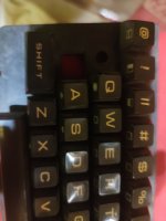
For keys you need someone else to answer that.
How do you actually know it works properly without running PETTESTER on it?
We were having problems yesterday with the machine - so I don't believe that it has 'fixed itself' overnight...
Have you also tested the cassette and IEEE488 ports?
Dave
How do you actually know it works properly without running PETTESTER on it?
We were having problems yesterday with the machine - so I don't believe that it has 'fixed itself' overnight...
Have you also tested the cassette and IEEE488 ports?
Dave
daver2
10k Member
If the VIA is not in that could account for your display issue. The VIA generates the GRAPHIC signal that is an address line input to the character generator. This line would be floating (not connected to anything) and and could be randomly picking up noise and changing the displayed character in random ways. This could get worse as the temperature changed.
It wouldn't account for the RAM test stopping though.
I would still advise putting the PETTESTER ROM back in and running it for about 20 passes of the DRAM test to be sure.
Running the PET itself for an hour with BASIC running doesn't stress test the memory...
Before we close this thread down - we need to discuss the learning that you take away from this experience...
Dave
dave_m
Veteran Member
Daver2,
The Addressing circuitry comprises the largest part of the PET system.
I hope our man has a new appreciation of the power of the NOP Generator if used properly and throughly.
His first usage of the NOP gadget on this PET missed the problem due to not checking all the address line connections.
What an important lesson for guys like me that take an occasional shortcut.