• Please review our updated Terms and Rules here

PET 4032 CRT Issue

BrainStruck

Member
Joined
Jun 5, 2020
Messages
23
Location
Jupiter, FL, USA
Hi,

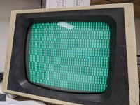
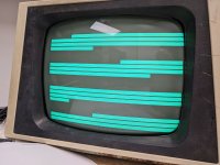
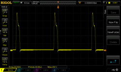
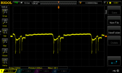
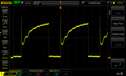
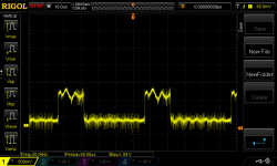
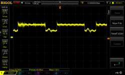
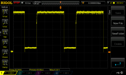
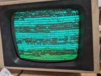
I'm in the process of restoring a PET 4032 and I cannot seem to get any video out of it. I'm using the pettest ROM right now to try to test the screen. I have horizontal and vertical sync signals. I have a video signal. I went through the Commodore 4000 Series Technical Manual and checked all 18 of the test points on the monitor and I'm getting the appropriate signals on an oscilloscope. The CRT filament is lit up but no matter how I adjust the brightness, sub brightness, and focus, I cannot seem to get any video.

What I have done:
Replaced all diodes including the zener diode on the high voltage hold down circuit
Replaced the polypropylene caps
Replaced the safety cap (0.015uf / 630v) next to the LOPT (this one smoked when I turned it on - typical for a RIFA)
Replaced 3 electrolytic caps that looked like they leaked


What I have NOT done:
Replaced the rest of the electrolytic caps that looked fine

Does anyone have any ideas?

Thanks,
Brian
 
For the screen to light up from beam current, it requires that EHT is present and that the grid of the crt is not too negative with respect to the cathode and that the cathode has satisfactory electron emission.

Initially at least, measure the grid and cathode voltage with the meter, with the brightness control on max.

Do you think there is any EHT present ? Most likely if the collector waveform on the HOT is ok, the EHT will be there.

Often, even without a EHT probe, or other ways to test that, small electrostatic charges like microscopic crackles can be heard when the CRT is powered up and sometimes powered off. You can also put a scope probe near the insulation of the EHT cable and see a transient deflection on the scope, when the set is powered or de-powered. Or suspend a small piece of plastic or polystyrene cup fragment near the EHT cable on a cotton thread and see if it moves with electrostatic forces when the set is powered. Or, after the set has been off for an hour or two, you can go under the EHT cap and find out if there is any residual stored charge in the crt bulb. Still the better way is a formal measurement with the appropriate EHT probe.
 
Last edited:
You've probably already had a look at most of the solder joints while replacing the caps and diodes, but might be worth having a close look for any dry solder joints. I had intermittent issues with one of the pets I worked on, and under a magnifying glass I could see cracks around the solder joints for the connector from the mainboard/psu.
 
You've probably already had a look at most of the solder joints while replacing the caps and diodes, but might be worth having a close look for any dry solder joints. I had intermittent issues with one of the pets I worked on, and under a magnifying glass I could see cracks around the solder joints for the connector from the mainboard/psu.
In both my 9" PET VDU's, the solder joints had 360 degree ring fractures on the pins of the connector on the VDU board, but I'm not sure if this is a problem on the bigger VDU model or not. Since the 18 test points have been scoped in the VDU, probably the H drive, V drive and video signals have made it into the VDU's circuitry.
 
Sorry for the late response. I wanted to get a high-voltage probe to check for EHT properly.

@Hugo Holden

I received my probe and the flyback transformer is putting out ~13.5KV.

I don't know what leads to test on the back of the tube and am hesitant to start probing connections without knowing for sure what I'm doing. I understand the concept of how a CRT works, but not enough to start probing on a running tube without some direction. There are 6 wires going to the back of the tube and they're labeled G1, G2, G4, E, H, and K.

E - Ground?
H - Heater
K - Cathode
G1 - ?
G2 - ?
G4 - ?

Can you please advise as to what the pinouts are or how I might be able to determine them? Am I testing them to each other or to ground?

@eight088

I double-checked all of the solder connections. They looked good, but I reflow some of them just in case. I did find that I left out D603 (oops), but after installing it, there was no difference in operation.

I've attached images of all of the scope tests on the control board for the horizontal side. I can retest and post vertical if you'd like.

Thanks,
Brian
 

Attachments

  • PXL_20221210_051134952.jpg
    PXL_20221210_051134952.jpg
    2.1 MB · Views: 4
  • Q721_C_18.png
    Q721_C_18.png
    36.9 KB · Views: 4
  • Q721_B_17.png
    Q721_B_17.png
    39.7 KB · Views: 3
  • Q711_C_16.png
    Q711_C_16.png
    38.3 KB · Views: 3
  • Q711_B_15.png
    Q711_B_15.png
    45.5 KB · Views: 3
  • Q701_B_14.png
    Q701_B_14.png
    37.5 KB · Views: 3
  • H_IN_13.png
    H_IN_13.png
    40.9 KB · Views: 4
ok, it is good the horizontal output stage is working fine , we should be able to work out why there is no emission. We also know the CRT's heater is glowing.

The CRT's base connectors are heater pins x2, cathode, G1 grid, A1 (first anode) and F(or A2 which is the focus electrode)

Check the crt's A1 anode voltage first. This is the first anode on the CRT base. If it has lost its A1 supply it will black out

After that, the two points with respect to ground/common that need to be tested are the grid and cathode of the CRT. These sit above ground at well under 100V. You can use your scope set to DC coupling or the meter.

With no video input the cathode (driven by the video output transistor, in this case acts more like a switch) pulls the cathode voltage (on text and graphic symbols close to ground) this reduces the CRT's grid to cathode voltage, normally it would take more than 30 to 40v negative on the grid to extinguish the beam (assuming say the cathode voltage was zero volts).

In any case if you set the brightness control to zero volts (full brightness) and check that the grid is zero or close to that with the meter, and look at the crts cathode (fill the screen with some text or symbol) voltage on the scope, that should tell us if the crt is getting correct drive.

I will reply later, away and not on a good computer.......

.....Can you post the link to the schematic of your particular VDU. If it is the 12" VDU, these have about 400V on the A1 anode, unlike the 9" version that only has 85V, so you need to be cautious of that. As I recall, these 12" VDU's are somewhat notorious for some fusible resistors on the secondary side of the horizontal output transformer, which are in series with the rectifiers there, going open circuit and killing the auxiliary supplies to the CRT.

I'm not sure if this is your VDU schematic as apparently there were some variants, but if it is I would check the 68R resistor in series with diode D752, if this had gone O/C it would kill the +400V rail.

 
Last edited:
This may be a complete red herring, but on my 3016, I have a slightly flakey connection from the motherboard for the female socket for the wiring to the monitor board - if I remove and replace the socket on the motherboard, it works fine (until the next time it doesn't).

I'm guessing if all the signals are present on the CRT end of things, then this may not be the problem, but have you checked continuity from the motherboard socket through the CRT wiring?

Can't hurt and it'll only take 5 minutes.

Colin.
 
@Hugo Holden That's the correct schematic, though the one on page 41 of (http://www.zimmers.net/anonftp/pub/...4000_Series_4016-4032_Technical_Reference.pdf) is more readable. You're right, R752 and R753 are bad - infinite resistance. I'm ordering new ones right now. Any idea what the metal tubes that I'm pointing at with a pen these resistors go through are called so I can order new ones?

@ScottishColin Thank you for your response. The connection between the CRT and motherboard shows good continuity.

It's frustrating to have to pay $10 in shipping every time I need $1.20 in parts 🤦‍♂️
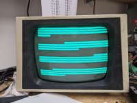
. I'm happy to be making progress though 😊. I'll report back when UPS drops off my Mouser order. Fingers crossed it gets here by Friday.

Thanks!
Brian
 

Attachments

  • PXL_20221213_221319482.jpg
    PXL_20221213_221319482.jpg
    1.2 MB · Views: 9
Those tubes are just a stand off to lift the resistors away from the board.

Most VDU's don't incorporate resistors, fusible or otherwise in this location on the auxiliary supplies. There can be some theoretical benefits to having a fuse in this location or a fusible resistor, if say there is a short on the high voltage rails. Likely though these particular notorious resistors failed through surface corrosion effects rather than being overloaded. Also, we do not know the exact specs of these particular resistors. If we did it might be possible to find an exact match as a spare part but I'm not sure if anyone has found that yet.

There is some theoretical use for resistance in the circuit there, when the VDU horizontal stage starts up as it limits the peak charging current of the filter capacitors on the supplies that these diodes and resistors feed.

If it were my VDU, I simply would replace them with standard 68R 1/4w or 1/8w metal film resistors. Standard resistors like this also act as fuses, especially the 1/8W variety and when they cook up they readily go O/C. Just mount the new ones a little away from the pcb surface with some clearance around them, so if they do cook up one day they won't burn anything nearby.

I think when you replace these your VDU will make a biblical recovery and return from the dead.
 
Last edited:
It's alive! Thank you Hugo!

Now I just need to figure out why I'm getting garbage on the screen.
 

Attachments

  • PXL_20221215_200841185.jpg
    PXL_20221215_200841185.jpg
    3.3 MB · Views: 19
If that's my initial PETTESTER video test screen I suspect you have a number of concurrent faults I am afraid.

What ICs in the video section have you got socketted? Is the character generator in an IC socket to start with, and then what about the video RAM itself?

Dave
 
If that's my initial PETTESTER video test screen I suspect you have a number of concurrent faults I am afraid.

What ICs in the video section have you got socketted? Is the character generator in an IC socket to start with, and then what about the video RAM itself?

Dave
I'm not even a little bit surprised 😄. This machine has fought me every step of the way.

The character ROM is an Intel 2716 and socket. I ran it in my Retro Chip Tester and it tests good. You'll notice in the pictures I attached that the video RAM is missing. I just removed it to run it through the RCT and both chips tested good. I ran out of time yesterday afternoon to go any farther than testing the video RAM. It's down 4 RAM chips at the moment but I don't think that's causing the issue. The memory that's installed tested good.

I'm hoping to find some time over the weekend to poke around it. I was just going to check voltages and probe around with a logic probe. I'm certainly open for suggestions if you have any ideas.

Thanks,
Brian
 

Attachments

  • PXL_20221215_224306788.jpg
    PXL_20221215_224306788.jpg
    4.2 MB · Views: 8
  • PXL_20221215_224302989.jpg
    PXL_20221215_224302989.jpg
    4.3 MB · Views: 8
When you say the character generator "tests good" have you checked the contents (or checksum) against what it should be?

Dave
 
The next thing I would try would be to remove the character generator EPROM and (with 8 low-valued - 120 Ohm ish resistors) connect the data outputs from the EPROM (at the vacated socket) to combinations of 0V/GND and +5V/VCC. this will drive the parallel to serial shift register that drives the video output and will cause every character cell on the screen to take up the same horizontal pattern of 8 bits.

Using this technique you can test the parallel to serial shift register (and all of the logic after it).

Likewise, if the video RAM is removed, you can do the same trick on the video RAM data outputs. This time you should observe a fully-formed character at each screen position - the character being based upon the PETSCII code that you have setup on the video RAM data outputs via the resistors.

This should fully check everything out after the video RAM.

Some of the characters in the image in post #10 are not valid characters stored in the character generator. It is just possible that what is on the screen is varying contents. As a result, a static photograph doesn't necessarily present the true reporesentation.


Dave
 
Last edited:
The next thing I would try would be to remove the character generator EPROM and (with 8 low-valued - 120 Ohm ish resistors) connect the data outputs from the EPROM (at the vacated socket) to combinations of 0V/GND and +5V/VCC. this will drive the parallel to serial shift register that drives the video output and will cause every character cell on the screen to take up the same horizontal pattern of 8 bits.

Using this technique you can test the parallel to serial shift register (and all of the logic after it).

Likewise, if the video RAM is removed, you can do the same trick on the video RAM data outputs. This time you should observe a fully-formed character at each screen position - the character being based upon the PETSCII code that you have setup on the video RAM data outputs via the resistors.

This should fully check everything out after the video RAM.


Dave
That is a good trick and it may well be worth making up some small pcb's with resistors and DIP switches on them, with thin pins (so they don't damage the sockets) and have these in the box of PET repair tools, along with PET testers and NOP Generators etc.
 
The next thing I would try would be to remove the character generator EPROM and (with 8 low-valued - 120 Ohm ish resistors) connect the data outputs from the EPROM (at the vacated socket) to combinations of 0V/GND and +5V/VCC. this will drive the parallel to serial shift register that drives the video output and will cause every character cell on the screen to take up the same horizontal pattern of 8 bits.

Using this technique you can test the parallel to serial shift register (and all of the logic after it).

Likewise, if the video RAM is removed, you can do the same trick on the video RAM data outputs. This time you should observe a fully-formed character at each screen position - the character being based upon the PETSCII code that you have setup on the video RAM data outputs via the resistors.

This should fully check everything out after the video RAM.

Some of the characters in the image in post #10 are not valid characters stored in the character generator. It is just possible that what is on the screen is varying contents. As a result, a static photograph doesn't necessarily present the true reporesentation.


Dave

I burned another CHAR ROM and verified it in the burner and the Retro Chip Tester. The file I used, I downloaded from Zimmer's.

I connected half the data lines from the Char ROM to ground and half to +5V and half to GND, then all to +5V and then all to GND. The results led me to believe that the problem is on the address line side. I tested all of the address lines going to the 74LS373 and they all checked good. I desoldered the 74LS373 and tested it in the Retro Chip Tester and it came back good. It was in pretty poor condition so I replaced it with a new one. I had already replaced the upstream 74LS244's. The RAM tested good. I still need to test continuity between the char ROM and crtc.
 

Attachments

  • PXL_20221220_012059777.jpg
    PXL_20221220_012059777.jpg
    3.2 MB · Views: 11
  • PXL_20221220_012959076.jpg
    PXL_20221220_012959076.jpg
    2.6 MB · Views: 11
  • PXL_20221220_013027303.jpg
    PXL_20221220_013027303.jpg
    2.8 MB · Views: 11
I am confused. What are the images taken of, because they are not correct?

Dave
These images are my testing results on the CHAR-ROM socket. The first image (PXL_20221220_012059777.jpg) is D0, D1, D2 and D6 pulled to GND and D3, D4, D5, and D6 pulled to +5V. The second image (PXL_20221220_012959076.jpg) is all of the data lines pulled to +5v, and the third image (PXL_20221220_013027303.jpg) is all of the pins pulled to GND. I used 220ohm resistors as that's what I normally use for pullup or pulldown resistors when working with Raspberry Pi's or Arduinos.

What should it look like?

The memory tested good and I installed sockets and inserted them in the sockets, but the pins on the actual memory chips are pretty short and if you move the board around too much they may fall out, so I ordered replacements.

Thanks,
Brian
 
The resistors on the data lines of the character generator SOCKET should be done with the character generator ROM REMOVED and not with it installed (if that is what you have done). Sorry if my post was not clear on this matter...

EVERY character displayed on the screen should be the same. Each character row comprises 8 dots horizontally. Which dots are illuminated are defined by the pull-up resistor. Dots that are not illuminated are defined by the pull-down resistor.

Let's do this test first...

Dave
I did the test on the socket without the ROM installed. It was a little clunky because I just put one end of the resistors in a socket hole and connected them to GND or +5V via an alligator clip. I'm going try to put together a perf board with pin headers that will fit the socket so I can use jumpers to change tie them to ground or +5V. This way I can try different combinations.

Brian
 
Back
Top