• Please review our updated Terms and Rules here

PET 8032 - No Chirp, No Cursor

Ah yes, I think upper case may not be permitted - but it is very weird that it did what it did! Let's leave that interesting fact for another day shall we. Let's squash one bug at any one time...

EDIT: It is all answered here: http://www.primrosebank.net/computers/pet/software/pet_sw_files.htm. This is the 'correct' behaviour! You can switch to upper case and graphics by typing the immediate command "print chr$(142)" - but then you loose the lower case characters - but you can now enter the graphics characters...

We already suspect that the first byte of the second bank of 16K of memory didn't work correctly - otherwise my PETTESTER would have detected valid memory there...

If you want to modify the program as follows:

135 input z$
140 goto 50

This will allow you to note down the error and then hit <CR> to perform the next test with the next test value.

Let's see if we have a consistent 'stuck value' shall we...

Already I am suspecting data bit 0 stuck at 0... But that is a poor statistical significance in 1 out of 1 test though.

Dave
 
Last edited:
Fair enough! I'll make that change and let you know what happens. Work is kicking my butt, so I don't have much time to work on this during the week, and by the time I do, you're already in bed. Thanks for staying with me on this. Really appreciate it.

Also, I didn't want to muddy the waters, but another thing happened that had me pretty frustrated last night. I started typing the little program and it froze up after a few lines. Reset and tried again, same thing. Reset a 3rd time and got a blank screen. Turns out my new CPU socket was already worn out. I had purchased 100 40-pin sockets on Ebay because they were much cheaper than my regular supplier. Well, you get what you pay for. I realize I've swapped the stock CPU and test board out a couple dozen times, but I wouldn't have thought it would wear out THAT fast! I'm thinking I'm going to throw out that whole batch of sockets and buy from my regular supplier, and chalk it up to a life lesson.
 
>>> ...and chalk it up to a life lesson.

Yep! If you have the option, buy from a 'reputable' source first...

Dave
 
Fair enough! I'll make that change and let you know what happens. Work is kicking my butt, so I don't have much time to work on this during the week, and by the time I do, you're already in bed. Thanks for staying with me on this. Really appreciate it.

Also, I didn't want to muddy the waters, but another thing happened that had me pretty frustrated last night. I started typing the little program and it froze up after a few lines. Reset and tried again, same thing. Reset a 3rd time and got a blank screen. Turns out my new CPU socket was already worn out. I had purchased 100 40-pin sockets on Ebay because they were much cheaper than my regular supplier. Well, you get what you pay for. I realize I've swapped the stock CPU and test board out a couple dozen times, but I wouldn't have thought it would wear out THAT fast! I'm thinking I'm going to throw out that whole batch of sockets and buy from my regular supplier, and chalk it up to a life lesson.

Usually, dual wipe sockets are a little more tolerant of slightly over-sized pins and recover better after insertion of any over sized pin.

Machine pin sockets are the worst type for easy damage with any pin over 0.45mm diameter.

Generally an actual IC pin is only in the order of 0.3mm thick and 0.45mm wide. Ideally nothing that exceeds this size is placed in any IC socket. Also, I lubricate all the sockets in my computers with Inox mx-3. This drastically reduces the wear if the IC is taken in and out many times.

(if you want to test socket claws, the best way to do it is to take a pin from a defunct IC, solder it to a small wire handle, lubricate it and use it to feel the socket's claw tension)

Machine pin sockets do very well with a 0.45mm diameter round pin, especially if they are lubricated. But unfortunately many adapters used to make add-ons that plug into IC sockets have larger diameter pins, often in the range 0.5 to 0.55mm. Once these have been put into a machine pin socket (and to some degree a dual wipe socket) the socket is then ruined for a standard IC. If standard 0.6 x 0.6mm header style square pins are pushed into a dual wipe socket, the socket is rendered useless and unreliable for an IC insertion later.

Recently we were alerted to a good type of round gold plated pin sold at Mouser suited to fitting to machine pin sockets, the long section of the pin is close to 0.45mm dia and they don't damage machine pin IC sockets, especially if lubricated.


Also, unfortunately the original PET sockets were only single wipe types and these are even less tolerant of multiple insertions, over sized pins and general wear.

If you look at a lot of machine pin sockets now, they have a tin plated pin with a small gold plated insert. The original Augat machine pin sockets though had Gold everywhere. It is still possible to find these sockets, when I built my Dazzler project, two boards loaded with many TTL IC's, I imported a stack of the good Augat 14 & 16 pin IC sockets for it from the USA, but they were not cheap and maybe x5 the price of the generic types out of the far east.

Here is a typical example of the high quality 40 pin socket with all gold pins by Augat, as you can see they are $5 each (but I think they are worth every penny also the gold makes for effortless soldering to the pcb):

 
Last edited:
.........also the smaller Augat sockets and other sizes are available from Dinos (a very helpful fellow at Qservice electronics, who has lots of Tek scope spare parts):


There is another type of IC socket that is wonderful, but I used up my stocks of them and I have no idea where they were made. They were a dual wipe type , but with gold plated claws/pins and they had a pale blue plastic shroud. I would dearly love to get more, if I could only find them. They were not the dark blue type made by Cambion.
 
Ah yes, I think upper case may not be permitted - but it is very weird that it did what it did! Let's leave that interesting fact for another day shall we. Let's squash one bug at any one time...

EDIT: It is all answered here: http://www.primrosebank.net/computers/pet/software/pet_sw_files.htm. This is the 'correct' behaviour! You can switch to upper case and graphics by typing the immediate command "print chr$(142)" - but then you loose the lower case characters - but you can now enter the graphics characters...

We already suspect that the first byte of the second bank of 16K of memory didn't work correctly - otherwise my PETTESTER would have detected valid memory there...

If you want to modify the program as follows:

135 input z$
140 goto 50

This will allow you to note down the error and then hit <CR> to perform the next test with the next test value.

Let's see if we have a consistent 'stuck value' shall we...

Already I am suspecting data bit 0 stuck at 0... But that is a poor statistical significance in 1 out of 1 test though.

Dave
You were correct. Bit 0 is stuck at 0. I printed the first 14 errors, then skipped to 32, 64, and 128. Is that ok? It was going to be a very lengthy list otherwise, and I thought I hopefully understood what we were trying to do. I switched it to binary so I could see the actual stuck bits. So it looks like bit 0, 3, 5 show "0" when they should be "1". Am I getting this right? Should I have done all 255 iterations?

Should be Found
00000001 00000000
00000011 00000010
00000101 00000100
00000111 00000110
00001000 00000000
00001001 00000000
00001010 00000010
00001011 00000010
00001100 00000100
00001101 00000100
00001110 00000110
00001111 00000110
00010001 00010000
00010010 00010000

Skipping to 32

00100000 00000000

Skipping to 64 (64 passed)

01000001 01000000

Skipping to 128 (128 passed)

10000001 10000000
 
Ok, knowing what bits are failing, I replaced UA18, which should have been upper RAM bit 0. Now it looks like Bit 0 is working, but bit 1 is stuck high.

Went ahead and replaced UA16 (bit 1), UA12 (bit 3), and UA8 (bit 5)

20220928_221316.jpg

So this is good news! Put the PETTEST ROM back in place, and I'll let it run overnight.
 
You learn quickly Padawan!

Yes, you were spot on with what we are trying to do.

Iterating from 0 to 255 is the ideal - but (if you suspect a particular fault) then some targeted testing (focussing on one data bit) would be the way to go.

Incidentally, your last test (what you claim to be 128) is actually 129 - but it makes no difference to the bit you are testing of course.

If you want to test one bit at a time there are a number of test patterns you can use:

The first test involves just setting one bit at a time (with the exception of 0 and 255 of course): 0, 1, 2, 4, 8, 16, 32, 64, 128, 255.

You can also try the bit shift starting with 0 and shifting a 1 bit (in hex - it is easier for me): 00, 01, 03, 07, 0F, 1F, 3F, 7F, FF.

You can also then try all bits set and shifting a zero bit in: FF, FE, FC, F8, F0, E0, C0, 80, 00.

These are ideal tests for single bit 'stuck at' faults.

You can use a BASIC DATA and READ statement for the specific patterns to test for rather than a loop. Of course, when you think you have fixed the problem, a loop from 0 to 255 would be the best test - and it should pass.

It is interesting that you appeared to get a faulty D1 though after replacing the D0 device.

Yes, let the PETTESTER loose on the 32K of RAM. This test is much more thorough for DRAM as it tests memory cell interactions. Read up on the MARCH-C memory test if you want to learn a bit more about how DRAM can fail.

Dave
 
Last edited:
I think the vertical scan height is set a little high on your VDU.

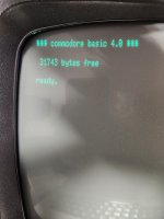
If you reduce it a little with the height control pot in the VDU, there will be a little less of a gap between the scan lines and the *** commodore basic 4.0 *** message won't be so close to the top of the display area on the VDU face.
 
You learn quickly Padawan!

Yes, you were spot on with what we are trying to do.

Iterating from 0 to 255 is the ideal - but (if you suspect a particular fault) then some targeted testing (focussing on one data bit) would be the way to go.

Incidentally, your last test (what you claim to be 128) is actually 129 - but it makes no difference to the bit you are testing of course.
Sorry if I didn't say that correctly. It looked to me like 128 passed, but 129 failed.
If you want to test one bit at a time there are a number of test patterns you can use:

The first test involves just setting one bit at a time (with the exception of 0 and 255 of course): 0, 1, 2, 4, 8, 16, 32, 64, 128, 255.

You can also try the bit shift starting with 0 and shifting a 1 bit (in hex - it is easier for me): 00, 01, 03, 07, 0F, 1F, 3F, 7F, FF.

You can also then try all bits set and shifting a zero bit in: FF, FE, FC, F8, F0, E0, C0, 80, 00.

These are ideal tests for single bit 'stuck at' faults.

You can use a BASIC DATA and READ statement for the specific patterns to test for rather than a loop. Of course, when you think you have fixed the problem, a loop from 0 to 255 would be the best test - and it should pass.

It is interesting that you appeared to get a faulty D1 though after replacing the D0 device.

Yes, let the PETTESTER loose on the 32K of RAM. This test is much more thorough for DRAM as it tests memory cell interactions. Read up on the MARCH-C memory test if you want to learn a bit more about how DRAM can fail.

Dave

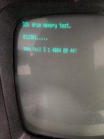
Thanks! Ok, let the PETTESTER RAM test run all night, and got a failure. Looking at your manual to see if I can interpret.
Looks like the address is 4004h, or 16388. That's near the bottom of the upper 16K RAM block.
80 means bit 3. Didn't I replace that one already?

Anyway, that's what I get if I read that right. Started the test over this morning, and we'll let it run all day and see if we get the same result.
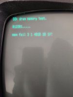
UPDATE: Home this morning for a staff meeting (of course I'm paying attention :)) and I got to see the results of the next run, and got the same result.

20220929_063223.jpg
 
Last edited:
4004h is in the second bank of 16K as you correctly surmise.

It's 80h - so that is data bit 7 (not sure where you got bit 3 from) - and you didn't change that device (according to my notes).

Yes, I am supposed to be reviewing a document... However, I was working over the weekend...

Dave
 
I think the vertical scan height is set a little high on your VDU.

If you reduce it a little with the height control pot in the VDU, there will be a little less of a gap between the scan lines and the *** commodore basic 4.0 *** message won't be so close to the top of the display area on the VDU face.
You're right, it definitely is set too high.
 
4004h is in the second bank of 16K as you correctly surmise.

It's 80h - so that is data bit 7 (not sure where you got bit 3 from) - and you didn't change that device (according to my notes).

Yes, I am supposed to be reviewing a document... However, I was working over the weekend...

Dave
Ah, now that's obvious. That's my fault for trying to squeeze this in on busy work days. I'm not sure what I was thinking either! I'll replace UA4 and see what happens.
 
When you have finished testing your RAM, you could make the ROM from my article and run the programs from it (you won't need the hardware adapter now BASIC is running). Two of those programs work by writing the whole memory with a checkerboard pattern. First (one of them) fills the whole memory from 0400h to 7FFFh with byte 00. Then after that it writes over alternate address locations with FF. (the other program does the reverse FF then 00). The idea behind this is to check that writing into memory cells doesn't alter byte values at other locations. Also, because there is a delay in inspecting that programmed pattern (done with the M/L monitor) it also helps confirm that the memory retention is good and that the DRAM IC's all have a normal refresh function , as this is another way that DRAM IC's can fail, aside from the other 4 ways their outputs can be defective.
 
The latest
When you have finished testing your RAM, you could make the ROM from my article and run the programs from it (you won't need the hardware adapter now BASIC is running). Two of those programs work by writing the whole memory with a checkerboard pattern. First (one of them) fills the whole memory from 0400h to 7FFFh with byte 00. Then after that it writes over alternate address locations with FF. (the other program does the reverse FF then 00). The idea behind this is to check that writing into memory cells doesn't alter byte values at other locations. Also, because there is a delay in inspecting that programmed pattern (done with the M/L monitor) it also helps confirm that the memory retention is good and that the DRAM IC's all have a normal refresh function , as this is another way that DRAM IC's can fail, aside from the other 4 ways their outputs can be defective.
interesting. This might be related to my next post. Seems like I'm chasing ghosts.
 
One thing to remember is that the error could be as a result of a marginal device elsewhere (data bus buffer, address multiplexer etc.). Repeating the test a few times would give you more data points - and make the results more statistically significant.

If you never get an error in the lower 16K bank of RAM, but always the upper bank, it is likely to be the RAM chip itself.

This just goes to show you how important it is to use the tests tools that are available. A very simple test will find simple faults (e.g. a "stuck at" fault). But long-term reliability is just as important, otherwise your machine will just crash in use.

Dave
 
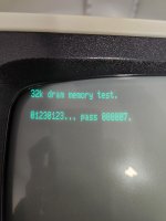
I had run that last test 3 times and it got stuck on the same address. Anyway, I was up to 5 4116 chips replaced in upper RAM block, and I said "Ok, that's enough of that!", and replaced them all. So far so good, but testing had only been going for about a half hour or so when I left for work.

My attitude comes from many years working on C64's, where if you have one bad RAM chip, more were sure to follow. This is especially true with the common failure of the stock C64 power brick, of which I have built and sold hundreds of my replacement C64 PS.

But that makes me wonder about what you said about a marginal device elsewhere, so we'll keep testing, and I'm going to run Hugo's tests as well. Especially since it's all the upper RAM block. That seems suspicious.

20220930_070735.jpg
 
Back
Top