• Please review our updated Terms and Rules here

Questions About the TU56 Tape Drive

NicolasF

Experienced Member
Joined
Jun 28, 2006
Messages
255
Location
Argentina
Hi,

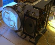
I would like to start testing our TU56 drive, but I have a lot of doubts about how to operate it.
What I did so far is to turn it on and connect it to the M868 board. Here is a list of questions:

1- Is it necessary to boot the machine in OS8 to test the drive? or is it possible to make it work without the OS?
2- If I set the front switches to either "REMOTE" or "LOCAL" both motors start spinning slowly in opossite directions, is this normal?
3- If I press either switch to rewind or forward nothing happens.
4- I noticed there are some switches close to the read/write heads, what are they for?
5- The light on the right side never turns on (I haven't tested if the light is ok)
6- If I'm able to boot the machine in OS8, how can I read the contents of a tape?

Thanks!
 
1- Is it necessary to boot the machine in OS8 to test the drive? or is it possible to make it work without the OS?

No, you can run the maindec testprograms for it. You have to load them trough the RIM loader.
http://so-much-stuff.com/pdp8/software/maindec.php Search for TD8E there

And if your drive passed the tests you can make your own tapes using DumpRest:
https://www.pdp8online.com/ftp/software/dumprest/

2- If I set the front switches to either "REMOTE" or "LOCAL" both motors start spinning slowly in opossite directions, is this normal?

Yes this is normal. In this way the tape is set on the right force and pulled back or forth for reading or (re)winding.

3- If I press either switch to rewind or forward nothing happens.

Put a tape on it. Then you will see the difference. Both motors have the same strength and
the tape stands still. When you push the rewind or forward the tape starts to move.
Both motors are powered to keep a bit force on the tape. But one motor gets more power
and so it is running in the desired direction. This only works in local mode.
On remote the OS controls the tape actions.

4- I noticed there are some switches close to the read/write heads, what are they for?

Not sure what you mean. You you mean the drive number switches for the address?

5- The light on the right side never turns on (I haven't tested if the light is ok)

This is turned on by the controller. Here you can see my 8E booting from a TU56
https://youtu.be/N17wbg80xUM OR on my 8M https://youtu.be/tOWt7LIOVJs
But defective bulbs is a common fault

6- If I'm able to boot the machine in OS8, how can I read the contents of a tape?

You have to tell OS8 that is has a TU56 tape drive first. Depending on your build.
Check the OS8 manual how to add these devices. Currently I'm trying to add my TU60 on OS8.
But I need some files to add it to OS. You can check RESOURC /E to see that devices are currently installed.

And get one of these to make your live much easier :D
http://so-much-stuff.com/pdp8/32KOmnibus/32KOmnibus.php

And I've seen other posts that you are restoring an 8E as well...
Make sure it runs all the maindecs to test the CUP and memory before even thinking
about restoring a TU56. Otherwise you will never be able to fix anything on it...

Regards, Roland
 
Last edited:
Hi Roland,

Thanks for your reply.

And I've seen other posts that you are restoring an 8E as well...
Make sure it runs all the maindecs to test the CUP and memory before even thinking
about restoring a TU56. Otherwise you will never be able to fix anything on it...

Yes I'm restoring the same machine and it's from a museum. What do you mean by "CUP"?
Do you know were I can download these programs? I found a bunch of test programs but I'm not sure which ones I can try...

4- I noticed there are some switches close to the read/write heads, what are they for?

Not sure what you mean. You you mean the drive number switches for the address?

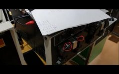
I'll attach a picture with the switches circled in red. TU56 switches.jpg

I read that the way of uploading the test programs is by first keying a RIM loader right? and then sending the binary through the serial board with TeraTerm or some similiar program.
I guess I'll have to run a memory check program because I cant execute any program from bank 0 (I guess its bank 0 all the EMA lights are off, right?)
I'm learning the very basics of how to operate the machine, nobody we know have any experience using this machine...
 
CUP == CPU... That's Roland typing too fast. Hi Roland :)...

Elsewhere you are stating problems with bank 0 - you need to fix that first...

As Roland states - you need to get a CPU and memory passing all of the MAINDECS first...

The 8E manuals identify the MAINDECs you will need.

You will need to run the CPU tests first (there are multiple of them. They start off simple and get more complex). E.g. Instruction tests part 2A and 2B followed by the random JMP then the random JMP/JMS then the random ISZ. Then you can start on the memory tests... If you have the EAE board set fitted, then you will also have to run instruction test 3A before the memory tests.

The more tests you run - for the longest period - the more sure you are of a working CPU. You must do this before starting on the peripherals (otherwise you won't know whether the fault is the peripheral or the CPU or the memory that the peripheral test is running out of)...

It sounds like you need to read the 8E manuals and understand them before attempting to do anything first...

Yes, RIM loader first (hand toggled in) then you may be able to load the next program directly (as long as it is RIM format) from the terminal emulator - or you may have to load the BIN loader followed by the program. Again, the instructions for the MAINDECs tell you what to do.

Have a look at maindec-08-d01c-d.pdf from http://so-much-stuff.com/pdp8/software/maindec.php. Beware though - ensure you get the binary tape with the same version of the PDF documentation that flies with it! I (unfortunately) picked the example for the PDP-8/I by mistake :-(! Let's go for this one instead then maindec-08-d02b-d.pdf :)! If you look in the RESTRICTIONS section it states that instruction set test 2A must have been run first.

Dave
 
Last edited:
What do you mean by "CUP"?

I meant CPU. Sorry, typo...


I'll attach a picture with the switches circled in red. View attachment 55364

These are not switches but DEC called them a wear plate. There is a little spring behind it. It guides the tape only.

Do you know were I can download these programs? I found a bunch of test programs but I'm not sure which ones I can try...
I read that the way of uploading the test programs is by first keying a RIM loader right? and then sending the binary through the serial board with TeraTerm or some similiar program.
I guess I'll have to run a memory check program because I cant execute any program from bank 0 (I guess its bank 0 all the EMA lights are off, right?)
I'm learning the very basics of how to operate the machine, nobody we know have any experience using this machine...

So you have to become the expert then :D At first you should run the toggle in tests.
These are in the bootloader / RAM expansion board to which I pointed you.
But you can also put them in by hand off course.
https://github.com/Roland-Huisman/M847-extended-version-V1.1/blob/master/Toggle in tests.pdf
You can run the tests from 20 to 26 at least.

Further all the important maindecs are in the link I gave you.
http://so-much-stuff.com/pdp8/software/maindec.php

And to prevent you from getting totally confused: These tests are loaded trough the BIN loader!
But the BIN loader is a RIM file...!!! So a piece of paper tape software.
So to load the BIN loader you must first toggle in the RIM loader.

After starting the RIM loader you load the BIN loader RIM papertape file.
After that you start the RIM loader and you can load the maindec test into the memory.
Then you can run the test.

To be honest, I found it very confusing and error prone... Those switches are fun for a while
but it's getting annoying after a while. And the same is for booting from several devices.
Every device has it's own bootstrap. That is why I designed the bootloader.
https://github.com/Roland-Huisman/M847-extended-version-V1.1/

https://youtu.be/0nqb3zyAv2g
https://youtu.be/xYt5kZuUb3A

Now you can load everything in a blink of an eye :D:D:D Even the BIN loader can put
into memory at once. So no further steps needed to load a maindec file.

Vincent Slyngstad merged my design with his nice 32KW RAM board.
http://so-much-stuff.com/pdp8/32KOmnibus/32KOmnibus.php

The PDP8 can handle 8 pages of 4Kilo Word of memory. You can switch on and off every single
bank to use your original amount of core memory and expand it to the maximum of 32K.

Regards, Roland
 
Last edited:
You can also look here for PDP-8e MAINDEC binary tapes and corresponding listings and PDF documentation: https://www.ak6dn.com/PDP-8/MAINDEC/
I've collected PDP-8e core diagnostics (CPU, MEMORY, EAE) and have BIN format tapes, RIM format tapes, disassembled PAL and LiSTings, and original DEC PDF scanned documents.

Don
 
Ok, I'm going to run the tests, first the toggle in ones and then the ones in RIM format. So I'm going to put the TU56 restoration on hold for now.
Here is a video of the M8655 test.

https://www.instagram.com/p/B1R9guYgtOr/

You can see that the first EMA light is on, because I can't make it run from bank 0.

Thanks!
 
You can also look here for PDP-8e MAINDEC binary tapes and corresponding listings and PDF documentation: https://www.ak6dn.com/PDP-8/MAINDEC/ I've collected PDP-8e core diagnostics (CPU, MEMORY, EAE) and have BIN format tapes, RIM format tapes, disassembled PAL and LiSTings, and original DEC PDF scanned documents.

Hi Don, That's a very nice collection!

You can see that the first EMA light is on, because I can't make it run from bank 0.

I agree with Dave, fix that bank 0 first... Good luck!
 
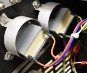
I recommend that you changes the big electrolytic capacitors sitting behind the front panel. I changed those to much smaller plastic ones.

And yes, fix the CPU first.
 
The ‘big capacitors’ will certainly need changing and probably already started to leak.

Anders - how did you manage to use ‘much smaller plastic ones’? These are motor run (not motor start) capacitors and I’ve not seen any particularly small ones at the rated voltage. The ones I used were almost exactly the same size as the originals, maybe even a bit wider.

I used those: https://eu.mouser.com/ProductDetail/80-R60EW61005000K 100uF/100V

DSC_1518_00002.jpg

I should really print some holders to those...
 
I would say, check the capacitors first. My drive is still running with the original capacitors.

Maybe an idea to think about...
I've restored many radio and TV sets and I always tried to keep the looks as original as possible. This is an example
of what I did in a Bush TV22 set. These capacitors are also mounted in a clamp at the bottom just like the TU56.

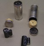
I used a pipe cutter to cut the capacitor at the point where it is in the clamp. Pulled the innards out and glued a
piece of wood in the bottom. Then there is still enough space to hide modern capacitors inside the old one.
Just drill a few little holes next to the terminals for the wires.

capacitor repair.jpg

When it's back into the clamp you never see the difference. :D

Bush TV22F 15.jpg

If you want to do this, please wear hand cloves and do it outside. Or better in a fume hood.
But it might be an idea to think about... (Oh and never open up oil can capacitors due possible PCBs in the oil...)

Regards, Roland
 
So is there consensus among the "electronitions" that these caps will do the job? And to verify that the only issue is rating, not that there is some magic "starting stuff" inside a start cap (versus a run cap)?

I could certainly use a couple of sets!
 
There is no such magic. I use them and Mattis use them (got the tip from him). I have been running my (well borrowed) TU56 for quit some time now and it works just perfect!
 
Starting capacitors are generally rated for intermittent use. Normally they’d be in circuit for (much) less than a second on a small/medium motor. Run capacitors are continuously rated as they are in circuit the whole time the motor is running. My view FWIW is that these capacitors are surprisingly small for continuous running. The only difference from a practical viewpoint is prospective lifetime. Hobbyist TU56s don’t generally run all that much.
 
As noted, extended capacitor lifetime isn't an issue for most of us, but I'd be interested in failure mode - I don't want to introduce another "RIFA situation" with spectacular fails to anticipate.
 
The classic failure mode is localised dielectric failure due either to overvoltage (eg supply/inductive spikes) or manufacturing deficiencies, but after that there are various possibilities. They tend to self heal by evaporating the conducting path, but it’s possible for the heat generated to become destructive for instance if the failure is repetitive or becomes resistive rather than open. Because dielectric failures aren’t uncommon there are some design approaches which try to minimise the chances of destructive failures. I’ve seen them swell up and emit a cloud of smelly smoke. As usual too big a subject to ramble on about here.
I’m sure that Murphy had heard of them too.
 
Back
Top