• Please review our updated Terms and Rules here

Repair/replace IBM 5110 power supply board (or seeking anyone experienced in similar work)

Probably this for step-up...

HiLetgo LTC1871 DC-DC Step Up Booster Converter 3-35VDC to 3.5-35VDC With LED Voltmeter DC-DC Step Up Module Power Supply Voltage Regulator

6A(max) out, 97% efficient -- only problem is: back ordered till end of the month :( Well, waiting for some thicker acrylic boards anyway.
 
The listed protections on the buck converters seem useful but not like anything that will avert the cascading failure I mentioned. One way to be more certain about this would be to just try some parallel-ganged converters and see what happens when you keep dialing up the load, though if the load wasn't designed for this setting, what works today isn't guaranteed tomorrow. Another would be to get in touch with the manufacturer and see what they think would happen if you tried to get 3 converters in parallel to satisfy up to 3X the rated maximum load. This kind of feedback may not be easy to obtain, but you never know.


Speaking of those kinds of modules, the ones you're buying seem to be mainly intended for use in applications like electronics workbenches and the like --- this probably accounts for why there aren't ways to "lock" the settings, or really for why they have configurable settings at all. You can find perhaps more suitable DC-DC converter options at electronics supply companies. Some of them are single through-hole parts that are remarkably compact, like this 6W-rated component here:

Here is its datasheet:

This unit actually emits +9V, but the 5110 MIM says that +9V is within the acceptable range for the +8.5V rail (just). This plus a bit of perf board and some wires might do the trick for you. It's less efficient than the module you've identified, but there may be similar ones that are better options. Again, it is quite small, and it is a single component... and there's no chance that you'll misconfigure it for, say, 15V by accident (zap!).


I'm never short on advice it seems but my last bit of advice for now is: obtain a test load. Thanks to your voltage and current measurements, you can work out what kind of big, beefy resistor you'll need in order for your test load to eat the nearly 25W that the 5110 eats from the +5V rail, and likewise for all the other rails. If you order those resistors and attach them appropriately to each voltage rail, you can test and adjust your power supply while it's serving up a 5110's worth of electric power, all without dealing with or potentially stressing the 5110. If you have an oscilloscope, you can check to see whether your loaded power supply has glitches or ripple, something it won't necessarily show without a load. Take care that you don't burn yourself on the resistors: they get mighty hot when they have to dissipate dozens of watts! You could keep a fan on them or try other cooling methods (add heat sinks etc.).

Here you can see my test load designed to emulate an Apple Lisa: https://photos.app.goo.gl/4vhXUVcr2JuCCEUTA

You can also spend money on "electronic loads", which will allow you to configure the current draw or power consumption and which often have fans that keep them cool. There are very expensive units for proper electronics labs, and then there are ones which are cousins to the buck converters you have already sourced, fairly cheap but probably good enough for a quick test. Here you can see me using a bunch of cheap electronic loads to test Voltmitten (plus I clipped onto one of the Lisa test load resistors for the -5V rail): https://photos.app.goo.gl/S63r2MQPXCVnHszq6

However, one thing that neither resistors nor bargain electronic loads can simulate are the ways that electromagnets, inductors, and motors consume power. These are called "inductive loads", while the ones you can easily test with a dummy load like I've described are called "resistive loads". For DC power, the only time these are different are when these loads switch on and off, which is indeed what happens when the tape drive's select magnets are activated or deactivated. Inductive loads have "momentum", in a manner of speaking. I'm afraid the easiest way you'll be able to see if your power supply replacement handles the inductive load needs of your tape-drive-equipped 5110 will simply be to try it out when the time comes. My guess is that it will be okay.
 
Last edited:
Are these "buck converters" possibly also "boost converters",

I was re-reading this from earlier -- as a matter of fact, yes they are. The 4A versions are listed as "boost buck" "step up down" converter. But the 12A version is listed only as a "buck" "step down" converter (I just noticed that today -- not sure if that's accurate, but that's how they're listed).


obtain a test load

I had looked around for an inexpensive way to make DC loads. The only thing really handy was an old HO electric train kit :D But I didn't want to pull that out. And an old digital clock, but probably not enough draw to be worth it.

How about just adding a 5A and 3A tiny automotive fuse after the buck converters?

No o-scope here :( Once I verify these spares do function, maybe I'll commit to a proper build with specific components, now that we know what is needed. With those smaller components - the PSU bay would have enough empty space, toss in a lithium battery and have the worlds first truly portable 5110 ? (hmm with inductive charging, so don't even have to drill in any charger hole?)

And if the internal CRT ends up not working - could I retro in a 5" LCD with a BNC adapter? Well, I don't want to tether all the way back to the external BNC - I'll have to explore how the video signal works on the internal wires.
EDIT: Oh gosh, someone does make a 5" LCD with BNC input.... Runs on 12V. I can't find the exact dimensions yet, but anyhow, looks like it could be done :)


Actually, once the PSU is sorted out (waiting for that 5V buck replacement), my next project is how to rig up a new keyboard. I don't want to pull the one out of my main working 5110. I'm hoping to rig something up using the serial or parallel port from the WindowsPC, and then effectively type input from that PC. I don't think the 5110 keyboard itself actually uses 8.5V. But, one thing at a timee.
 
Last edited:
How about just adding a 5A and 3A tiny automotive fuse after the buck converters?

I suspect it's not so necessary and, for several of the things you'd be using a test load to check, not so helpful.

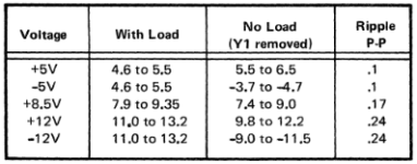
Fuses prevent problems due to excess current. Some of the conditions I was speaking of have to do with the quality of the voltage that your power supply provides. Note this table from PDF page 64:

voltage.png

Even if your power supply solution produces the correct voltages on average, the specification here has a column about "ripple". No power supply can keep the voltage exactly on target --- the regulation always wavers around the precise value, with more wavering occurring (usually) as load is added and removed from the rail. (Technically, even gates turning on and off inside of an IC changes the load, although individually these are not enough to matter --- things like the status LEDs on the front panel may be just big enough to cause the smallest detectable blip, and then go up from there.)

Anyway, this table is saying that the amount of wavering --- "ripple" --- for each rail must be limited. The difference between the lowest voltage observed on the +5V rail and the highest voltage on that rail can't exceed 0.1V. (That's the "peak-to-peak" measurement or P-P for short.)

An oscilloscope is probably the easiest way to measure ripple. But you may also find that the datasheets for the Mean Well power supplies and DC-DC converters that you choose also specify the maximum amount of ripple they will generate when they are under the kind of load that your 5110 will produce. If it's less than what's in this table, that's good news!

(Of course these datasheets might also say that the quality guarantees they make about ripple and other characteristics apply only to resistive loads. But... at some point even I have to say that you can worry about things a bit too much!)

Fuses meanwhile just don't care about ripple. They also don't care about other, less orderly kinds of voltage noise that you might find coming out of a power supply, like spikes and other transients.

With those smaller components - the PSU bay would have enough empty space, toss in a lithium battery and have the worlds first truly portable 5110 ? (hmm with inductive charging, so don't even have to drill in any charger hole?)

You'll have to find some way to power the AC loads inside the machine, so an inverter will be necessary too. We could have another very long discussion about what kind of inverter would be suitable for this task, and the characteristics and downsides of really cheap ones.

In a previous post, you'd wondered whether the fan may have mainly been for dust control. I am pretty certain that it's necessary for cooling --- note that by your measurements, the DC power consumption amounts to 21.5W of +5V, 20.4W of +8.5V, and 28.8W of +12V. Passive cooling of net 70W would not be impossible, but I think things would look a whole lot more heat-sinky than they do.
 
Last edited:
Oh, I said "some of the conditions". What were the other conditions? Basics really: just making sure that your power supply can handle the load without falling over.
 
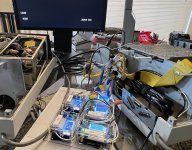
Swapped the 5V/4A boost buck with a 12A step-down model (that 12A model doesn't have an onboard temperature probe, but after several minutes being on it still didn't even feel warm to me; however it's LCD was indicating 4.8Amps, where previously it was ~4.3).

I felt comfortable enough to swap in the "good" Executive ROS and give the system a full startup.

The internal CRT still isn't working - but on the external video, it was a real joy to see it cycle through the ROS CRC checks and then flip over to the BASIC prompt on the first startup!

No keyboard yet on this one, but the cursor was blinking, register switch works, L32/R32 works, reset works. So it's a viable bench tester - and it can all be fit inside the original PSU bay. Not sure if I'll do that just yet.

IMG_1757A.jpg


For the 5110 unit on the left, I'll wait for the MeansWell PSU and do the boost to 8.5V on that (after testing things out standalone first).


I haven't completely given up on the original PSU, I really suspect it's just 1 or 2 diodes that have gone bad on it. But I'm happy these alternatives are available for under $100 in parts.
 
That's nice to see! I agree that it's worth trying to repair the original PSU. I hope you'll share your experience if you give it a shot!
 
You'll have to find some way to power the AC loads inside the machine, so an inverter will be necessary too.

Good point, I was ignoring the fans altogether. Regarding the cooling-utility of those fans - I was just recalling before around the 1980s, there was a lot more in-office-smoking and less air-conditioning back then.

Also recall, the only fan in the IBM 5150 was in its PSU, or things like the PET and TRS-80's had no fan at all.
 
Ok, the boost buck came early, so the past few evenings I've assembled the 2nd PSU replacement for an IBM 5110 based on the MeansWell PSU.

I believe this would also work for an IBM 5100 (same dimensions and the Y1 connector pinouts on the A1 board is the same).

BOARD
I ordered a thicker acrylic boards from Professional Plastics. They weren't very expensive, except they had a minimum order of $25, so I've ended up with 4 boards.

The dimensions I use were:

0.187 THICK CLEAR EXTRUDED ACRYLIC FILM-MASKED SHEET [Per Piece]
Size: 10.62" X 6.10" @ +/- 0.031

[ approximately 4.7mm thick -- I think the next step up was 5.5mm thick and that would have worked fine, but I went conservative and selected the 4.7mm one ]

The size of the cut was spot on to the original PSU PCB, so very happy with that. Mounting holes were easy, just drilled at a medium speed (at least to start) - no cracks, light sanding to clean up the bores a bit.

ACTUAL PSU
The actual AC/DC conversion it from a pre-built MeanWell PSU. A little bit long (thus more weight), but passive (no fans).
MeanWell RQ-128B, which provides +5V +12V -5V -12V (from DigitKey).

To "boost" the 5V line to 8.5V, I used the following generic device:
HiLetgo LTC1871 DC-DC Step Up Booster Converter 3-35VDC to 3.5-35VDC With LED Voltmeter DC-DC Step Up Module Power Supply Voltage Regulator

The LED just shows the input or output voltage (no temperature), and the LED can be turned off (once have the desired conversion, can turn off the LED to eliminate any red light and slightly reduce some draw).

WORK
From there, it is making a bunch of spade connectors to be compatible with the original Y1 wiring harness (two different sizes). It was a compromise between making these longer-than-needed for convenience (when it comes to actually installing inside the IBM 5110 PSU bay area), but not too long that it overly clutters up that PSU bay. Then used a clear rubber "boot" between each connection, so the metal of certain wires never inadvertently touches another. So stripping, crimping, testing.


Previously I used a set of buck-boost DC adapters, and that still works in another 5110. But for being about the same cost (still under 100 bucks in parts), I do like this updated version better (a slightly smaller version of the RQ-128B would be nice -- but the one here is still plenty compact enough).


Here's how it turned out. I am trusting it enough to close things up and make it the permanent PSU I used for this particular 5110. Next, I'm waiting for an o-scope to arrive to start looking into building a keyboard replacement (or at least some way to drive inputs).

1) Size comparison with stock IBM 5110 PSU
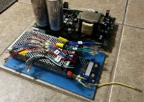
IMG_1948A.jpg


2) Fitment complete. Testing all the Y1 pins before actually connecting to the A1 board (also tested before actually fitting the board into the bay). The top screws are all fine, but behind the external ports, I actually missed on the lower holes (drilled them slightly too high, but not a huge deal since the external ports are securely screwed down and hold the bottom half of the PSU anyway).
IMG_1958A.jpg

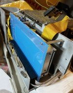
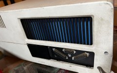
3) Still a prototype, to verify fit and drilled placements, etc. I left the blue sticker on one side of the acrylic, giving this effect from the backside of the unit (a nice "Big Blue" effect, although I think that IBM slogan didn't really start until the 1980s)
IMG_1967A.jpg

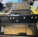
4) The system boots with this PSU, that has been secured into the same spot as the stock PSU! Here it is at the BASIC prompt. Now to start work on a keyboard alternative. (some might recognize this one, I used it in the PALM assembler/machine code demo).
IMG_1964A.jpg


I do have another 5110 that is 100% all original parts, down to every screw (and original price receipt and metal serial plaque). So it's fun having a 2nd to be more experimental with.
 
Last edited:
Nice, it's good to find an alternative!

On the boost converter, it looks like voltage is set by a trimmer, so it can't "forget" someday that it's supposed to be +8.5V... that's good.
 
Small note, the MeanWell did come set to 230V, so did have to open it and flip it to 115V (it has a yellow sticker on its case as a reminder about that).

And yes, glad the boost just has a little trimmer, and no bulky knob. :)
 
Back
Top