• Please review our updated Terms and Rules here

Replacements for 'blowing' rice-paper capacitors on Osborne1

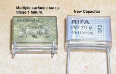
I have attached a photo of a stage 1 failure. The capacitor surface has multiple fine cracks.

At this point there is only mild water absorption & swelling and close inspection shows the surface is only slightly bulged.

In stage 2 there is moderate body swelling and destruction of more surface insulation.

Stage 3 it smokes.

So if you see stage 1, replace the capacitor and avoid future trouble, at least for some decades.

Also, about that Sewing Machine story. You will sometimes see X2 capacitors put across switches in series with line operated appliances, some industrial machines (how about a motor operated factory guillotine) as contact arc suppression. It is a very very bad idea. Because these capacitors can fail to a low resistance and spontaneously start up the appliance (as I witnessed myself), even though they are in theory supposed to fail open.
 

Attachments

  • CRACKS.jpg
    CRACKS.jpg
    218.5 KB · Views: 12
On mine, only the RIFAs looked bad, so I left the normal ones alone. The system was working before I found the caps in this state, though.

1663168274914.jpeg1663168312632.jpeg

The caps I ended up using were the smaller size, but as mentioned the board had the holes for this size ready to go:

1663168464591.png
 
On mine, only the RIFAs looked bad, so I left the normal ones alone. The system was working before I found the caps in this state, though.

View attachment 1246118View attachment 1246119

The caps I ended up using were the smaller size, but as mentioned the board had the holes for this size ready to go:

View attachment 1246120
I'm trying to get mine working. No picture on CRT, but have lights on the floppy drive when turned on. Doubt the RIFA caps are the problem, but replacing them first before they blow. Oddly, mine had Y RIFA caps in the 0.01uF caps and Y2 100nF (0.1uF) for the larger cap. Any ideas why everyone seems to be using X RIFA caps but mine had Y caps? Looks like someone had previously replaced the caps, so maybe the used the wrong type?


Also, Any idea what the loose connector is that is labeled "115V"? Wanting to make sure that shouldn't be connected to anything.


Finally, any idea where to start troubleshooting the lack of video signal to CRT? Checking for cracked solder joints around the flyback or board connector. Never worked one of these, but very familiar with working on Compact Macs with CRTs and it usually was a bad solder joint on the connectors. Thanks for any assistance!
 
Is the external video plug installed?
"If after a few moments nothing appears, check the small
opening below the monitor and slightly to the right, labeled
EXT VIDEO. A rectangular-shaped plug should securely fit this
slot."
 
The difference between X and Y safety capacitors is the failure mode. X capacitors are constructed to fail short--that is, to blow the fuse on the equipment. Y capacitors are constructed to fail open--and so are used as bypass to neutral/ground. Y capacitors have traditionally been more expensive than X ones, which is why you'll see a mix of them on line filtering. However, Y caps can be used in both applications.
 
Is the external video plug installed?
"If after a few moments nothing appears, check the small
opening below the monitor and slightly to the right, labeled
EXT VIDEO. A rectangular-shaped plug should securely fit this
slot."
Yes, it has the external video plug in place.
 
Is the external video plug installed?
"If after a few moments nothing appears, check the small
opening below the monitor and slightly to the right, labeled
EXT VIDEO. A rectangular-shaped plug should securely fit this
slot."

I'll add some information to explain. There's a small slot just below and to the right of the monitor marked as the external monitor port. The video signals are on the bottom of the plug and the video to the internal monitor is on the top of the plug - and there's a requirement to connect the bottom pins to the top pins to get the monitor working, otherwise no signal gets to the monitor. The plug being referred to is just a jumper plug that is installed when the external monitor isn't being used, but without it, there is no picture.

Also, the computer should beep once when power is applied, and then even if you don't have video, the next thing it asks is to press return to boot - Just hit return and if the left drive lights up, the computer is most likely working even if there's no video.

If it doesn't beep, then check the board. They run off of Gnd, 5v and 12v into the power pins line this... 12v 5v GND GND GND 5v 12v - And the 5v and 12v lines AREN'T CONNECTED TO EACH OTHER, so you need to run 5v and 12v to both input pins. I think they do that so that the power saving battery doesn't drive the entire motherboard, but it's not a good idea, because it's all looped at the PSU anyway, and the -5v for the RAM comes from the other 12v line... Though maybe it doesn't need -5v if the 4116's are not running and are just holding memory and that design might be intentional.

Anyway, Long story short, you can run the O1 main board from a PC power supply from the floppy cable if you connect it up correctly.

Regards
David

Oh, the 115v line is because it's a COTS power supply they used at the time... It's for if you don't have some kind of external select like the O1 has... Don't connect it anywhere - just leave it floating. Also, if the PSU isn't working, and you're not up to fixing it, you can get a small 5v and 12v switching PSU pretty cheap thats about the same size in case you need to replace it - but they are pretty hard PSUs I've noticed... The only bad failure I've seen was when the caps mentioned burst open and sprayed hot molten metal all over the transistor next to the 0,1uF filter cap... And I didn't notice. It didn't work. It also burned a hole in the two nearest electrolytics, so I replaced all three nearby electrolytics, and took the transistor out - I didn't have a replacement so I scraped all the aluminium off and cleaned up the melted transistor plastic, and it tested OK, so put it back and it worked this time :) They seem to be pretty robustly designed SMPSs from what I can see.
Thanks for the awesome information. I thought that jumper plug was just a cap to cover an external video connector. Neat idea to make it a set of jumpers when no external video is plugged in. I don't get a beep on powering it on. I get a faint / flickering light on the right drive when powered on, so I'm probably going to recap the power supply, see that I'm getting good 12 and 5v power, and go from there. I'll let you know how I make out. Appreciate all the great info!
 
Thanks for the awesome information. I thought that jumper plug was just a cap to cover an external video connector. Neat idea to make it a set of jumpers when no external video is plugged in. I don't get a beep on powering it on. I get a faint / flickering light on the right drive when powered on, so I'm probably going to recap the power supply, see that I'm getting good 12 and 5v power, and go from there. I'll let you know how I make out. Appreciate all the great info!
Happy to assist - I too am new to Osborne and was fortunate this was mentioned to me -

Also, rather than trying to fix the PSU, if the computer isn't beeping, I would recommend bypassing it altogether while testing - It only needs a good stable 5v and 12v at around 2A each supply, and should produce video. The monitor works off of 12v from the computer board directly, so that's all that's required for testing.

Once you get the beep and the screen is working, you can repair the PSU from a known working position.

Recapping the filters is a good idea, but the other caps on your PSU are most likely working, so are not likely to be at fault, and the PSU will often work even with the filter caps all blown and damaged. As such, using an alternative PSU to confirm the logic board and monitor are both good is a great way to start.

Also, check the main PCB for shorts between 5v and GND and 12v and GND since the tantalums might well have shorted, and could explain main PCB failures - If these have shorted they will prevent the PSU from starting up and reaching voltage, and might explain the outcome you're seeing on the drives.

You can power up the PSU once you've replaced the filter caps without the main logic board attached to determine if it's working OK - should be a little over 5v and 12v measured at the plug where it goes into the computer. The SMPS itself is a bit dangerous and does have a number of exposed points that are live so be careful.

Regards
David
 
Back
Top