• Please review our updated Terms and Rules here

Rev 04 Apple II+ - No Clock signal

falter

Veteran Member
Joined
Jan 22, 2011
Messages
6,573
Location
Vancouver, BC
Hi guys,

I have a low serial Apple II+I picked up a while ago that is completely stone dead - nothing comes up on screen, no beeps. I have a known good power supply attached, but have observed there is no clock signal anywhere. I tried swapping crystals, but same thing. Also swapped a 175 and 7486 to no effect. I'm wondering, am I down to the two transistors Q1 and Q2 at this point? Is there anything else that could prevent the clock from operating?
 
Check to ensure all the ICs (and especially the two you replaced) are oriented correctly. Really easy to put them in backwards when fixing the II+
 
Not sure what I did but I did find B1 bad, and I have clock signal now and can see the CPU resetting.. but still no picture or beep.
 
Done. I also did a complete swap of chips from known good board to this one.. nada. The clock signal is being erratic. I can see it consistently being emitted from pin 8 of B2 (7486), then it goes over to B1 74175.. I can see it there but pin 7 where clock 0 should be coming out is held low. I got this to go away once by swapping the 175 with another.. but it's back to being held low. There is no clock getting over to the 7408 at b11 and thus nothing to the CPU. Best guess is a broken trace or such.
 
Done. I also did a complete swap of chips from known good board to this one.. nada. The clock signal is being erratic. I can see it consistently being emitted from pin 8 of B2 (7486), then it goes over to B1 74175.. I can see it there but pin 7 where clock 0 should be coming out is held low. I got this to go away once by swapping the 175 with another.. but it's back to being held low. There is no clock getting over to the 7408 at b11 and thus nothing to the CPU. Best guess is a broken trace or such.
Easy way to tell would be to test by placing an ohm meter / continuity tester on pin 7 of B1 and pin 2 of B11.

That said pin 7 of B1 is also routed to pin 2 of C1, pin 5 of D2, pin 10 of B12, and pin 1 of A2. Perhaps one of these chips is causing the erratic behavior you're observing from the phase 0 clock? Before performing the continuity test you may want to try pulling them one by one and seeing if the clock appears. If not then you know they won't affect the continuity test (since they'll all be out)

Curious: Do you have the phase 1 clock?
 
I believe I have phase 1.

Phase 0 though is really confusing. I've powered up and down a whole bunch of times any maybe once every 5 times I get clock out to B11 and up to CPU.. but usually nothing.. like something is pulling things high. I have clock going into pin 9 on the 74175.. but pin 7 is pulled high even if I pull every chip otherwise connected to it as per what you posted. It's got me thinking something is shorted. I should try bending out pin 7 and seeing what it does unconnected to its socket.
 
Did you perform the suggested continuity test between pin 7 of B1 and pin 2 of B11? You may also want to perform a continuity test between pin 7 of B1 (or pin 2 of B11) and ground. If that doesn't help then your idea of bending out pin 7 and checking for clock signal is a good one.
 
Yeah the continuity is perfect between pin 7 B1 and pin 2 B11.. and no nothing ties to ground. Bent out pin 7... still high. Maybe I have 3 bad 175s (I've swapped 3 in B1 so far) but I doubt it. I'm missing something here.
 
If all the chips connected to pin 7 of B1 were removed and there are no shorts to ground then it stands to reason there is an issue with B1 or something leading up to it. Since the system will not operate without the clock perhaps you should swap out B1 with a known good part.

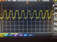
I also have a question. When I measured this pin on my Apple II Plus it was a 7MHz frequency (see scope pic) and not the 1MHz phase 0 frequency. I believe that both phase 0 and 1 are derived from this 7MHz frequency it seems odd you would have phase 1 and not phase 0 if this frequency isn't present.


7MHz Clock Signal from B1 pin 7.JPG
 
I just checked and actually I don't have either Phase 0 or Phase 1. Every now and again when I start up I do. System still doesn't post or produce video but clock can be seen. I've been examining the board and testing sockets carefully to see if something isn't making a good connection or if there are any breaks somewhere. I've tested 3 different 74175s in the same location (all were known good) and still same results. More and more i feel like this is a board issue and not IC issue.
 
Another weird thing with this machine is it came with a purple ceramic character generator. It's the correct part number but it's not plastic like what you usually see. I swapped in a plastic one just in case but no change.
 
I borrowed one of my other II+ machines and tested the char gen, CPU, and 74175 chips in it. They all work fine. I actually tested all three 74175s and they all work great. So the issue isn't that IC. It's something else in the chain.. socket, board itself, transistor.. I don't know. Going to keep following the schematic around until I find it.
 
Hopefully it won't be a lot of effort to check continuity. At least not for the paths connecting pin 7 of B1 to the other chips. Is the frequency you're observing, when present, ~7MHz?
 
Seems to be 7mhz yeah.

I'm just baffled. I cannot figure out what is preventing the signal. I thought maybe i had a culprit when I discovered a sliver of metal bridging pins in the slots.. but nope.. not that.
 
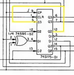
What is the signal on B1 pins 5 and 12? Pin 5 is the input for the D latch output on pin 7. Pin 12 is the input for the D latch output on pin 10 (which in turn is the input on pin 5). If B1 pins 5 / 10 are low that would result in a low output on pin 7. The same with B1 pin 12, if it's being held low the output on pin 10 will be low thus the input on pin 5 will be low resulting in a low output on pin 7.

You should also check the level on B1 pin 1 to ensure it is not being held low.
 
Something I discovered by accident. I was using my logic probe on B1 and accidentally shorted pins 6 and 7.. and then I got a clock at pin 7 all the way up to the CPU. Still no life otherwise. The clock ran for a while and then shut down. I shorted again, same thing.. runs for several minutes or less and then stops.
 
So here's something I'm not sure is involved.. I was looking at the outputs of the 7486 at B2.. it has a clock signal at pins 3 and 8, but not 6. 6 seems stuck high. 6 should have a clock. I followed the schematic and found pin 6 connected to pins 9 and 10 of D13 and D14. I pulled D13 and swapped for a different chip.. pin 6 went low. I swapped D14, no change. Put the exact chip that had been in D13 at the start, pin 6 of B1 went high again.

Not sure if that third output of B2 has any impact at all on anything.
 
B1 pin 5 is high, pins 10 and 12 are low.
This needs to be investigated. Per the schematic (taken from the Apple II reference manual) B1 pins 5 and 10 are connected together. Unless there's an open circuit between these two pins one cannot be low and the other high (or the schematic is incorrect which, as I discovered in a different thread, was the case with one of the ICs. I think this is unlikely as the schematic diagram matches the 74LS175 part datasheet regarding pinouts and function). There should be a 1.02MHz clock on both pins.

Furthermore B1 pin 12 is also suspect in that it should have a 1.02MHz clock signal.

IMPORTANT NOTE: In post #10 I mentioned B1 pin 7 had a 7MHz frequency on it (and the scope picture shows that). I made an error with the orientation of the chip and was not measuring pin 7 but rather pin 15. I caught this error when measuring B1 pins 5, 10, and 12 for today's responses. I rechecked pin 7 and it is 1.02MHz. Aside from this error everything else remains the same. Apologies to the mistake (I am not able to edit post #10 so thought I would point out the error here).

What instrument are you using to make these signal measurements?

Schematic - IC B1.jpg
 
Last edited:
Back
Top