• Please review our updated Terms and Rules here

RS-232 won’t send data on a Model 4?

Ackshooerry

New Member
Joined
Nov 14, 2022
Messages
8
I have a TRS-80 Model 4 that can’t/won’t send data over RS-232. I can connect to a Windows 10 computer just fine using Putty, and I can paste data in Putty and watch it appear on the TRS-80, but I can’t do the opposite. I have also tried jumpering pins 2&3 to see if I can get a local echo, but that doesn’t work either. Here are some specifics:
  • I am running LS-DOS 6.3
  • I type “set *cl com/dvr” upon booting
  • I am using xt4 as my terminal software
Is there any obvious issue that might be easy to fix? I am using 2 goteks so I should be able to use whatever other software is out there. I don’t have MAL, but maybe I should hunt that down? I kind of doubt this is a software issue. Is there a way to write some simple BASIC code to test out the port’s ability to send data?

That question on BASIC brings me to another question. Is there anyway this problem could be memory related, and is there anyway to test that? I have most of the documentation for the computer (but not the technical reference) and I have tried various things I find. However, basically any code that uses sys() calls seems to fail. I assumed that that was because I don’t really know what I am doing, but now I wonder if there could be some type of memory issue.
 
Welcome to the forum @Ackshooerry !

I don't have any Tandy-specific knowledge, unfortunately, but there are plenty of folks here who do.

You might want to introduce yourself, in the appropriate area.

- Alex
 
If you have 4 non Gate Array model
First: I would inspect is the flat ribbon cable on the card, often they rot out. or the pins get bent when people reinsert them.
Second: if you jump 2/3 and get no local echo it could be a chip issue. (IE the TR1602 could be faulty) I would look at Pages 169-173 and sweet if the output is stuck High or if there is actually a bit reset performed properly to enable transmit.
I attached that portion of the model 4 technical manual to this response.

Also if you have a 4 Gate Array Model with no separate RS232C board
looking at the quick Sams computer facts manual on the model 4, re serial post issues it does give two quick things to try
A) Check connect J3 for good connections (previously mentioned)
B) Check timing IC (U9) and uart IC (U82) by substitution.

Also found this in the Sams to perform further testing
1668520734317.png
 

Attachments

  • TRS-80 Model 4 RS232 Technical.pdf
    433.4 KB · Views: 4
Last edited:
If you have 4 non Gate Array model
First: I would inspect is the flat ribbon cable on the card, often they rot out. or the pins get bent when people reinsert them.
Second: if you jump 2/3 and get no local echo it could be a chip issue. (IE the TR1602 could be faulty) I would look at Pages 169-173 and sweet if the output is stuck High or if there is actually a bit reset performed properly to enable transmit.
I attached that portion of the model 4 technical manual to this response.
Hopefully this doesn’t display my ignorance too much, but are you are about the TR1602? My board has a UART labeled COM8018. According to a random old catalog I found online, that is pin compatible with TR1865, not TR1602. I just want to make sure I use the correct replacement.
 
Last edited:
I would be more inclined to suspect the buffer chips before the UART, as they are the parts likely to take the damage from a wiring/transient incident. I think the Model 4 uses the common 1488/1489 pair.
 
When it comes down to IC's there were so many variations through the ages I would not be able to answer the TR1602 vs TR1865 differences, but a quick look at both specification sheets (attached below) seems to indicate they are compatible to each other.

I have only repaired two of these RS232C boards in the past and both problematic chips were the U6/U10 Quad D Flipflop Chips 74LS174 you could test those first
Eudimorphodon has a point, and suggest checking on the U3/U4 Buffer chips as well.

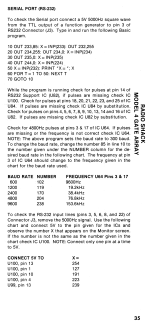
Sams Service Manual on the RS232C suggests the following procedure to find the issue:

SERIAL PORT (RS-232 BOARD)
Check for - 12.8V at pin 4, 12.0V at pin 3 and 5.0V at pin 1 of Connector P3 on the Serial Interface board.
If any of the voltages are not correct, refer to the "POWER SUPPLY" section of this Troubleshooting Guide.
Check Connector P2 on the Serial Interface board and Connector J8 on the System board for good connections and check the ribbon cable for possible breaks.

To check the Serial Interface board, connect a 5-volt, 5000Hz square wave from the TTL output of a Function Generator to pin 10 of Line Receiver IC (U11). Type in and
run the following Basic program.

10 OUT 233,85: X = INP(233): OUT 232,255
20 OUT 234,255: OUT 234,0: X = INP(234)
30 OUT 235,0: X = INP(235)
40 OUT 224,0: X=INP(224)
50X = INP(232): PRINT "X=";X
60FORT = 1 TO 50: NEXT T
70 GOTO 10

While the program is running, check for pulses at pins 1, 4 thru 7, 9 thru 12 and 15 of the Address Decoder IC (U8). If pulses are missing at pin 1 of IC U8, check Decoder IC (U40)
on the System board. If pulses are missing at pin 15 of IC U8, check Decoder IC (U41) on the System board. If pulses are missing at pins 4 thru 7 or 9 thru 12 of IC U8, check IC U8.

Check for pulses at pins 1, 2 and 4 of IC U7. If pulses are missing at pins 1, 2 or 4 of IC U7, check IC U7. If pulses are present at pins 1,2 and 4 of IC U7, check for 4800Hz pulses
at pins 3 and 17 of the Baud Rate Generator IC (U1). If pulses are missing or the frequency is not correct at pin 3 or 17 of IC U1, check IC U1. Note: The above program sets the
baud rate to 300 baud. To change the baud rate, change the number 85 in line 10 of the above program to the number given under the NUMBER column for the desired baud rate
in the following chart. The frequency at pins 3 and 17 of IC U1 should change to the frequency given in the chart for the baud rate used.

XZVMqRQ.png


Check for pulses at pins 2, 5, 7, 10, 12 and 15 of Flip/Flop IC (U6). If pulses are missing at any of the pins check IC U6. If pulses are present at pins 2, 5, 7, 10, 12 and 15 of IC U6,
check for pulses at pins 3, 6, 8 and 11 of IC U12. If pulses are missing at any of the pins check IC U12. If pulses are present at pins 3, 6, 8 and 11 of IC U12, check for pulses at
pin 3 of IC U16. If pulses are missing at pin 3 check IC U16.

Check for pulses at pins 5 thru 15, 19, 21, 22, 25 and 34 of UART IC (U2). If pulses are missing at pins 21 or 34 of IC U2 check IC U7. If pulses are missing at pins 5 thru 15, 19, 22 or
25 of IC U2, check IC U2. If pulses are present at pins 5 thru 15, 19, 21, 22, 25 and 34 of IC U2 check for pulses at pin 11 of IC U16. If pulses are missing at pin 11 check IC U16.
Check for pulses at pin 9 of Flip/Flop IC (U10) and pin 1 of Tri-State Buffer IC (U9). If pulses are missing at pin 9 of IC U10, check Decoder IC (U41) on the System board. If pulses
are missing at pin 1 of IC U9, check Decoder IC (U40) on the System board.

To check the RS-232 input lines (pins 3, 5, 6, 8 and 22 of Connector P1), remove the 5000Hz signal from pin 10 of IC U11. Use the following chart and connect 5.0V to the pin given
for Line Receiver ICs U11 or U15 and observe the number X that appears on the Monitor screen. If the number is not the same as the number given in the chart check the buffer IC
being tested (IC U11 or U15)and check Tri-State Buffer (U5). Note:

Connect only one pin at a time to 5.0V.

OvvdIwZ.png


To check the interrupt select lines, pins 5, 7 and 10 of Flip/Flop IC (U10), stop the above program (press the BREAK key), type OUT 224,112 and press the ENTER key.
Check for a High logic reading at pins 5, 7 and 10 of IC U10. If any of the logic readings are not correct, check IC U10.
NOTE: The Computer will lock up after OUT 224,112 is entered. Press the RESET button to reset the Computer.
 

Attachments

  • TR1602-WesternDigital.pdf
    483.9 KB · Views: 1
  • TR1863-1865.pdf
    384.9 KB · Views: 2
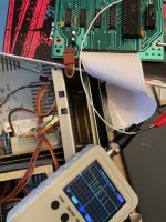
Thank you for your help. I am very much an amateur at this, but I’ll try my best to follow these instructions. I’m the meantime, I hooked up my $30 oscilloscope from Amazon to the UART at the TSO pin, which I believe should be line the data comes out on, and I can definitely see a signal when I press a key on the keyboard (see picture). I noticed that the signal is high (5V) when nothing is being sent and low (0V) when there is a signal, which is the opposite of how I understand the RS-232 standard works (negative voltage in standby and positive voltage when transmitting). Presumably, this is evidence that the UART is working correctly, and the issue lies with one of the other chips on the board.

Again, thanks for your help.


5B88027E-104B-4D09-A362-85B804D59A67.jpeg
 
I’m the meantime, I hooked up my $30 oscilloscope from Amazon to the UART at the TSO pin, which I believe should be line the data comes out on

Do you mean the TRO pin? (pin 25)


I noticed that the signal is high (5V) when nothing is being sent and low (0V) when there is a signal, which is the opposite of how I understand the RS-232 standard works (negative voltage in standby and positive voltage when transmitting). Presumably, this is evidence that the UART is working correctly, and the issue lies with one of the other chips on the board.

The UART has TTL level input-outputs so if you're seeing activity on pin 25 I'd say this is pretty good evidence your UART is fine. I'd definitely look at the MC1488 line driver at this point. If the schematic I have is correct you should be seeing the activity coming from pin 25 on the UART going *in* to pin 12 on MC1488, U16, and coming out shifted to RS-232 levels on pin 11. If that's *not* happening, check the status of pin 13 on U16; that's the output of a 74LS174 latch mapped to port EAH, D2. If it's not set to "high" then data transmission is disabled. (I assume whatever software you used to set the UART parameters already set this bit correctly?)
 
Last edited:
When it comes down to IC's there were so many variations through the ages I would not be able to answer the TR1602 vs TR1865 differences, but a quick look at both specification sheets (attached below) seems to indicate they are compatible to each other.

It looks like the main difference between the TR1602 and the 1865 is the latter has been slightly tweaked to have more "according to Hoyle" TTL-level logic levels. (And is also capable of being clocked *much* faster.) You could probably get away with swapping them for this application, though.
 
Do you mean the TRO pin? (pin 25) ... If the schematic I have is correct you should be seeing the activity coming from pin 25 on the UART going *in* to pin 12 on MC1488, U16, and coming out shifted to RS-232 levels on pin 11. If that's *not* happening, check the status of pin 13 on U16; that's the output of a 74LS174 latch mapped to port EAH, D2. If it's not set to "high" then data transmission is disabled.
Yes, I meant TRO (typo); definitely pin 25. I confirmed that pin 12 on U16 matches the output from pin 25 on the UART. I also confirmed that pin 13 on U16 is high (+5V). However, there is no signal on pin 11. I'm going to read up on some documentation of how these chips are supposed to work. If nothing else, this has been very educational.
 
Those results sound suspiciously like your MC1488 is dead. It's not uncommon for those chips to be the thing that gets the magic smoke let out of it if a serial line gets cross-wired or zapped by a phone line transient that makes it through the modem or whatever.

Check both power connections on that chip first, however. I think it's at least theoretically possible you could lose the -12v in the Model 4 and the serial port is the only thing that would fail.
 
I confirmed -12V on pin 1 of the 1488. I'm going to order a new chip and I'll let you know if it solves the problem. Wish me luck with my (de-)soldering efforts.
 
I have a TRS-80 Model 4 that can’t/won’t send data over RS-232. I can connect to a Windows 10 computer just fine using Putty, and I can paste data in Putty and watch it appear on the TRS-80, but I can’t do the opposite. I have also tried jumpering pins 2&3 to see if I can get a local echo, but that doesn’t work either. Here are some specifics:
  • I am running LS-DOS 6.3
  • I type “set *cl com/dvr” upon booting
  • I am using xt4 as my terminal software
Is there any obvious issue that might be easy to fix? I am using 2 goteks so I should be able to use whatever other software is out there. I don’t have MAL, but maybe I should hunt that down? I kind of doubt this is a software issue. Is there a way to write some simple BASIC code to test out the port’s ability to send data?

That question on BASIC brings me to another question. Is there anyway this problem could be memory related, and is there anyway to test that? I have most of the documentation for the computer (but not the technical reference) and I have tried various things I find. However, basically any code that uses sys() calls seems to fail. I assumed that that was because I don’t really know what I am doing, but now I wonder if there could be some type of memory issue.
When trying make a simple RS232 interface ALWAYS jumped...

2 - 3
6 - 8 - 20

Do this on both ends.

If using 9 pin connectors such as IBM just convert these 25 pin interface signals to appropriate 9 pin signals (sorry I don't remember without looking).

This will make sure software and hardware both see DTR, CD, CTS, RTS etc when they need to see them.

After that you can use 3 wires between devices (xmit, rec, gnd).

Maybe you have already covered this in your post but I didn't see it.

In TRSDOS you can use SETCOM to ignore or set these signals but that only works in your app uses driver correctly.

Handshake signals are often cause of hangs like this.

Good luck!
 
Also as far as manipulating RS232 with BASIC....

COM port *cl is opened just like a file and assigned a buffer number you supply like 1.

You can then print #1,"Hello world!"

In reverse you will use BASIC INPUT command and input from this buffer number just like keyboard.
 
I just wanted to pop back in and say thanks to all the help I received in this thread. I bought a replacement 1488 chip on eBay for $2, and I was able to de-solder and replace the old chip without breaking anything. Everything seems to work fine now. I was even able to check out some BBSs using a WiRSa Wi-Fi adapter. Thanks again!
 
Back
Top