• Please review our updated Terms and Rules here

Sinclair spectrum +2 gray model video issues (not transistor related, probably)

My belts and the DIN plug arrived.

I've turned all three of the 2N3904s around and inserted them180 out from the positions indicated by the screen printing. I've checked them over again and measurements now show that the collectors of TR5 and TR7 do now go to +5V which is correct according to the diagram, also TR4's emitter goes (Via 75R of resistance) to the composite output pin. - The display with RGB video is really nice, none of the characteristic smearing or swirling or 'dot crawl' which is associated with the composite or RF output. There is some very slight vertical banding on the overall white background and I think this is probably due to the presence of digital noise on the supply lines to the video circuitry but I am going to leave that for now.

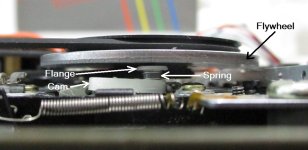
On changing the belts I nearly had a disaster because I went to replace both belts (as you should) and although the original small belt was very thin and came out through the gap between the underside of the flywheel and the other hardware underneath it, the new small belt was the regular thickness and didn't want to go through the little gap which the original thin belt had passed through easily. I also thought I was going to have trouble getting the small belt to ride on the pulley ring on the underside of the flywheel because I could not see what it was doing so for both of those reasons I decided to release and lift out the flywheel. There is a plastic split washer clipped around the flywheel spindle on the other side of the deck so I carefully removed that to free the flywheel and started to pull it away from the deck. Just as it was about to come free something went Kachow! and a couple of parts flew past my nose, but by a small miracle I had the wit and the luck to see where they went and what they were: namely, a little white plastic flange and a spring. You can see what I'm talking about by looking at the attached image.

There was only one place these could really go so I put them back on there and routed the belts and put the flywheel back in but something didn't seem right as the spring was holding the white flange against the underside of the flywheel, liable to cause both drag, noise, and quite possibly a lot of static build up. Eventually, I realised the little flange is a friction fit on the black pin or spike which it sits on so there should be at least a 1mm gap between the white flange and the underside of the flywheel, the flange should not be touching the underside of the flywheel. I originally did not push the white flange down far enough / hard enough when I refitted it so the spring pushed it off the pin / spike and held it against the underside of the flywheel. The job of the flange is to hold the spring in a compressed state so it puts pressure on the elongated white cam below it. When you operate the pause button on and off that cam oscillates between two alternate positions so if I had lost those parts I just wouldn't have a working pause button.

Another thing I looked at was the RS232 / MIDI socket, now these are, or appear to be, the type of socket which a British style telephone plug plugs into. However, and I remember this now, they are NOT exactly the same and a standard British telephone plug won't fit into them without modification, basically the standard plug is too high / thick to fit into these Amstrad specified sockets. You can make a standard UK telephone plug fit, but you have to file / shave certain parts off the plug in order for the plug to be able to be inserted into the sockets. At work we have some sockets of a very similar type and the same pinout / footprint which DO accept standard British phone plugs without modification and I am seriously considering fitting a pair of those - only trouble is they are white, whereas the original sockets are black. Even when you have modified your plug to fit, you then have another problem - how to put it onto a cable, as this requires an expensive specialised tool. The workaround for that is to buy not just a plug but a British phone patch lead - a cable with British telephone plugs already fitted on each end. Cut the lead exactly in half and carefully work on the plug, filing it until it is an easy fit into the socket. If you make a mess of it, try again with the other plug - that's why you cut the cable in half, rather than cutting one plug off one end.

The other thing to maybe consider is to try to identify a 6-contact RJ11 modular socket with the same pinout / footprint and replace these troublesome sockets with a pair of those instead.


SpectrumPlus2_Grey_Flywheel.jpg
 
Last edited:
A brief update on the RS232 / MIDI plug situation, I have been informed that the correct plug is designated type '631W', whereas a 'Normal' British 6-contact telephone plug is a 631A - the four-contact 431A is much more common but these would not be suitable even for modification as the plug does need to have 6 contacts. I should have said above that if buying a patch cable it needs to have six cable cores and 6-contact plugs on the ends.
 
I think the same thing happened to me when I was first servicing this computer when I first got it about a year ago. Something in the tape unit went flying. I never found it, it's probably in some dusty corner of my basement but I'd have no idea what it even looks like. As a result my pause button doesn't work. Well it pauses but it doesn't stay latched down, you have to hold it.

I find it strange that my TR7, which is a 2N3904 appears to be correctly installed (consistent with the screen printing). The next time I have this computer open I might just triple check that I'm not confusing the collector with the emitter.

As for RGB output my plan is to try connecting it to VGA and running it on this Lynx monitor which should accept it as it accepts a similar RGB signal from my Atari ST. But since I already have an ST -> VGA cable connected there and I don't want to bother disconnecting it, the cable I'm going to build (when the parts come in) will be a patch cable between the spectrum and that "ST -> VGA" cable. So it'll be 8 pin male din on one end and 13 pin female in on the other.

I found out the noise from my tape unit is the motor. Earlier I said it's quiet when it's not in the case, well that's not exactly true. What I now know is that it's quiet when it's upside down. I separated the motor from the rest of the unit and ran it off of a bench power supply and the noise coming from it varies with the angle the motor is positioned, right-side-up it's loud and upside-down it's quiet. I looked to see if there's any way I can lubricate the motor (maybe a drop or two of machine oil) or open it up but it looked pretty well sealed.

So my options there are:
1) do nothing, just live with it being noisy
2) source a replacement motor. My concern here is if the replacement is just as old (even if it's NOS), it may have its internal grease just as dried up and it won't work any better than the one I have. Alternatively if I have to transfer the plastic pulley from the old motor to the new I may break it in the process (old, brittle, plastics)
3) I could just remove the main belt, which does cut down some on the noise. The motor is still spinning but without the belt it is about 30% quieter. But I like to keep things original if possible and some day I may want to use an actual tape, maybe to save a game or if I'm playing around in basic and want to save my program
4) Disconnect the power to the motor. In theory this might work since I'm using a car adapter but a) all of the issues in #3 above, and b) I noticed the speccy seems to know when I pressed play based of the border color change so I'm wondering if it knows that based on power flowing to the motor and if it needs to sense that in order for it to start listening for data.

As far as the rs232 port, probably for me unless I could use it to telnet into BBS's I don't think I'd find a use for it so I probably won't look into ways to use it. In theory though it might at least work at 300 baud.

Meanwhile this led me to another project, restoring a broken 2.5" HDD based MP3 player I've had sitting around for about 8 years or so waiting to be fixed. This "NEO-25" player I bought new back in the early 2000's. I thought it would be perfect for putting wav & mp3 files on for loading into the speccy, as well as other vintage computers that use tapes. Since it uses a standard laptop IDE hard drive I should be able to use a compact flash adapter with it. I would prefer to use this over other mp3 players that are on the market today as it has a nice directory-based browsing operating system rather than artist/album type navigation based on ID3 tags. That way I can have different directories for CoCo, MC-10, TI-99/4A, Speccy, etc...

With some help of some folks over on this forum I was able to get the LCD screen working (mostly) again.
 
The missing parts you are looking for are the ones I have labelled 'Spring' and 'Flange' in the image attached to post #61. If you lost them a year ago I would say your chances of recovering them are now slim unless, like me, you never tidy anything up. I think what happens here is that the effort required to get the small belt out through the little gap between the flywheel and the flange often results in the flange popping off the pin that it should stay pushed down onto. Given your experience and mine my suggestion for anyone else about to change the small belt is: Unplug the cassette deck from the main PCB and take out the five screws which secure it and its PCB to the top casing. Also remove the single screw which holds the small power LED PCB in place and then remove the whole deck, its PCB and the small power PCB from the top housing of the computer.

Then, find yourself a large, clear plastic bag and put the deck and your hands and arms inside the bag and work on it like that. If anything, especially a spring, makes a sudden departure, it will be caught by the bag. This is my go-to technique whenever I work on something which might turn into an exploded diagram of itself, i.e., something I suspect may have springs inside it. I didn't do it with this deck because in my whole lifetime of working on things like this I have never encountered a spring-loaded something lurking underneath a cassette flywheel. I live and learn.

The only potential pitfall with using an MP3 player to output audio to an old computer like this is that the player may not output sufficient audio output voltage for the computer to be able to 'hear' it. This is because the maximum audio output power from players which are only ever meant to be used with headphones is intentionally limited to prevent users from destroying their hearing - so - it may work, you just have to try it. I had this problem with a Creative Zen Nano MP3 player and I had to use an elaborate technical trick to make the audio output loud enough to be usable - I've described that method a couple of times before in this forum so I won't go over it again.

It will do no harm to disconnect the motor. When the computer is in 'waiting for a program to be played' mode, it changes the border colour whenever it gets a whiff of some audio, any audio. Starting the motor may very well cause a 'click' on the audio, but that's all. The computer's ability to 'hear' audio is definitely not dependent on there being a running motor.

You've mentioned using the monitor's VGA input with an Atari ST - that's definitely with ST low and medium resolution, not just hi-res? It's well known that you can use a VGA monitor as a poor man's SM124 (Atari mono monitor) but there are very few VGA monitors which can operate down to 60Hz or 50Hz. If that one does I would be interested to know the exact model details, etc.
 
Last edited:
On the Atari ST, yeah that's just low & medium res.

I'll have to test the mp3 player's audio output to see if it's sufficient. The player isn't fully restored yet but it's operable enough to test if I run a power cable to it. I know I tried to load a tape into a TI-99/4A off my cell phone and I couldn't get it loud enough but I was able to get it to work by feeding the audio out of the cell phone, into a tape recorder (on record, with no tape in it), and then back out from there into the computer. The tape recorder amplified it enough to work but it was tricky getting the volume set just right between the phone & the tape recorder so that it was sufficiently loud but not over-modulated. So far the speccy seems to be pretty resilient with loading data from tape and hasn't had any issues yet.

What I might do is put a small switch on the power going to the tape motor, that way it can be switched on if the need pops up but otherwise I can not have it on and not making noise when I don't need it.
 
So I got the cable / din connector to try to make the video cable and was just diagramming the various pinouts when I found this page: http://fizyka.umk.pl/~jacek/zx/doc/man128/sp128p03.html this shows that the R, G, and B are TTL level, that means digital right?
If so I can't use VGA as those are analog signals. Although I do have an RGB2HDMI I used on a C128, so I might be able to wire it into that instead.
I tried to look at the R, G, and B signals on the scope to see if they were square or sine but it sort of looks... like a really sloppy square, maybe?
 
You can run 'digital' RGB into analogue RGB inputs if you have some attenuation, which normally means a resistor in series with each of R, G, B.

Have a look at this page on Paul Farrow's site (the whole site has a lot of useful info for ZX81 / Spectrum fans) - the first part shows the internal circuit diagram of the +2 in the video output area, and the second part shows a suggested schematic for a +2 RGB out to analogue-RGB-in lead. You can see that there are 150R resistors in series with R, G, B.


The section with the regulator won't be required in your case as that is specific to SCART (There is an input pin on the SCART connector which can be used to 'inform' the display whether the incoming signal should be treated as Composite Video incoming , or RGB + Composite Sync incoming). Since your monitor's input is not via a SCART interface that part of the circuit is irrelevant for you, and if you are going into a VGA input (15 pin three row sub-D, right?) you will need to provide the VGA monitor with separate syncs probably from Spectrum Csync to Monitor Hsync and from Spectrum Vsync to Monitor Vsync (as noted earlier, the Spectrum does not have a specific Hsync output on the monitor socket).

We are on slightly new territory for me here as I have never known a VGA monitor which would accept such low refresh rates on the VGA input. I think NEC used to make a few monitors which were described as 'Multisync' but I think even they used separate standard video and VGA inputs (I could be wrong).
 
Last edited:
I've found several sites which all agree that on a VGA R, G, or B signal line the minimum voltage is 0V (none of that colour) and the maximum voltage is 0.7V (Maximum intensity for that colour) - so yes, the output range from the Spectrum's R, G and B outputs probably need dropper resistors in series.

The Sync inputs on VGA on the other hand appear to be TTL-Level. I have noticed problems in the past with e.g. Atari ST trying to drive some (not all) VGA Hsync and Vsync inputs which happen to have 75R internal termination resistors. Where the Sync outputs from the computer are just normal logic IC outputs (as they are on the ST) that is too low a resistance for those outputs to be able to drive. On the Spectrum +2 the Vsync output is from an LS TTL IC and the Csync output is from an output on the ULA, both via 75R resistors, I am not sure whether either of those will have sufficient drive strength to drive a Sync input which is 75R terminated.

However, you should be OK because you have already said that the monitor works with the sync outputs from your ST, therefore hopefully it will work with the sync outputs from the +2.
 
Interesting. Since this is all experimental I think I'll wire all this up the through a breadboard, if I can get a usable signal then I'll make it into a complete cable.
I'm also wondering if those 150 ohm resistors are already in place in the scart cable I was trying to use way back in the beginning, which would explain why I couldn't measure continuity through the cable. I guess it's easy enough to tell, find some pins with 150 ohms resistance.
 
Last edited:
If the cable you are referring to is a DIN to SCART cable with an actual SCART male plug on the end I would expect that you will find the series resistors (if any) inside the SCART plug as there is more room there. A typical SCART plug has a 'collar' at one corner through which the cable enters, if you unscrew that collar anticlockwise and slide it back over the cable you should be able to prise open the two halves of the SCART plug cover. They are hinged, like a clam shell, along the side furthest from the entry point.

The reason it's not so straightforward is because Peritel, the other standard supported by the machine, is actually a digital interface, the colours are only ON or OFF but there is an additional 'Bright' signal on the interface which can tell the Peritel display to select one of two intensity levels, thereby doubling the number of 'shades' of each colour.

In the +2 the 'bright'' signal is internally superimposed on the R, G, and B signals so that the three, originally completely digital R, G, B outputs have two possible levels of intensity by the time they reach the R, G and B outputs on the +2. In this sense you can think of the R, G, B outputs from the +2 with the links set for 'Standard' (Not Peritel) as being 'semi-analogue', however they still need reducing further before they are fed to a true analogue R, G, or B input and that is what the series resistors in the cable are for.
 
Last edited:
Oh okay that may explain the sloppy square wave I saw on the scope. It does look like the r, g, and b as well as the composite pins on the scart cable have ~150 ohms resistance. I was thinking of taking advantage of the two cables together (8 pin din to scart + scart breakout) but unfortunately the pin for v-sync isn't on the breakout.

Doesn't look like I'll have any time this weekend to work on it further and work has been pretty hectic lately too so it might be a while before I can carve out some time. But now that you told me about the resistors I think I can probably come up with something. The big question is will it be something the monitor will be able to work with.
 
The only problem I can really anticipate is the absence of an actual Hsync output on the Spectrum. I can only hope that if you feed Csync in there instead, the Hsync input circuit will be smart enough to recognise which are frame pulses and which are line pulses. Otherwise you might have to add a Sync separator to split only the Hsync from the Csync.
 
Well I had some time this weekend to make the cable, using a breadboard between the 8-bin (spectrum) side and the 13 pin din side (which then connects to my existing 13-pin to vga cable I had previously made to use on my ST)
First hooking up the ST to ensure that cable is still hooked up and working (it is)

But my cable on the spectrum isn't working at all, monitor reports "no signal". Double checked that my wiring matches my diagram and that there's continuity from pin to pin. Other than the resistance on the red being slightly higher than expected (180 ohms), possibly due to the makeshift way I attached solid wire to the ends of the wires so that I can shove them into the breadboard, everything is fine on that end. Anyway even if the r, g, and/or b was not connected or the resistance was off as long as the sync signals are coming through I'd expect the "no signal" message to go away.

So I'm going to go over my diagram again to make sure I didn't draw it wrong, and assuming I didn't I'll probably order one of those sync separators as you suggested. If that doesn't work then most likely it's just not a signal this monitor will recognize.

I do have an RGB2HDMI which I used with my C128, there might be a possibility there but to be honest I'm not that unhappy with the dirty composite I have, it's usable and sort of feels like using a CoCo through RF.
 
Update: I double checked my diagram and I did have it wrong. I had numbered the pins on the 13 pin din from the solder side. But I hate soldering din connectors it's a pain, even when using the "potato method". So instead I bought a 13 pin extension cable and cut off the female end and used that. Which means when I mapped out the pins to each wire on that everything was mirror image.

After fixing that I reconnected it and it works great! Crystal clear picture!

The only drawback now is that because the monitor it set to VGA there's no audio, so I need to pipe the audio into separate speakers. Oh well.
 
Glad you resolved your RGB problem. I don't like soldering DIN plugs either, all too easy to overheat the pins and they start drifting out of position. My own solution for that is to get a matching socket, put that in a vice / vise and plug the plug into the socket, which helps to keep the pins aligned even if they get a bit too hot. Does your monitor have an internal audio amp and speakers? If so they should be enabled even in VGA mode. I have had several CRT monitors and at least two flat screens which had internal speakers + amp.
 
Yeah the monitor has speakers and audio inputs but there doesn't seem to be an audio input for VGA, only for video 1 and video 2 which are both composite inputs. I had the same issue with my ST what I did was run the audio cable over to a PC speaker set up which has two inputs:

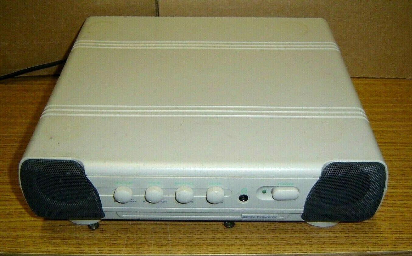
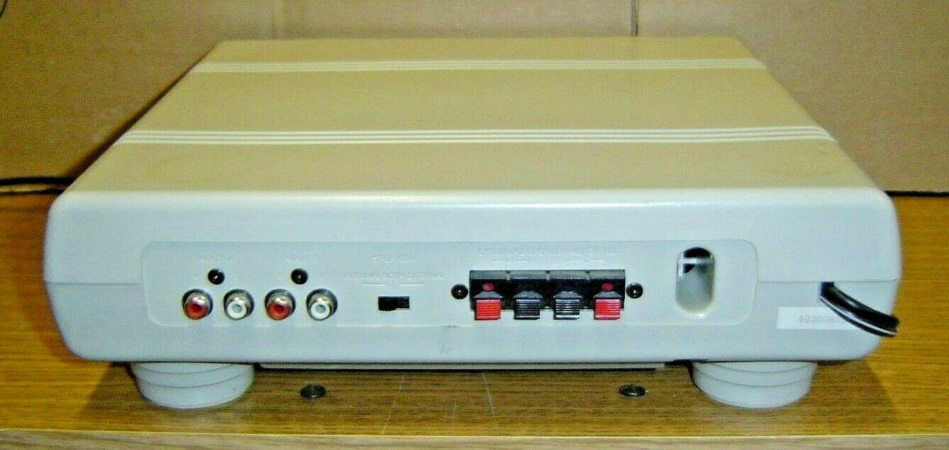
(I stole these images off of a current ebay auction but this is the same as what I'm using)
speakers01.jpg
speakers02.jpg


So the PC (a Pentium 2 @ 300 mhz) can use one input and the ST can use the other. It's a little awkward since the speakers are on my left and the screen is on my right but it works.

I'm thinking of getting a pair of RCA Y-cables so that the ST input can be shared with the audio cable for the spectrum. It'd be pretty messy if I tried to run both the ST and spectrum at the same time but I wouldn't do that (I don't even have space to do that).
 
Try connecting the Spectrum audio-out jack to either the 'video 1' audio input or the 'video 2' audio input when the monitor is in VGA input mode. I would be surprised if audio is not routed from one of those two audio inputs through the amp and to the speakers when the monitor is in VGA-input mode. Apologies if you have already tried it, but it does not seem rational for the monitor designer to include an audio amp and speakers and then NOT allow that facility to be used in VGA mode.
 
You are correct, I got a flashlight back there and took a close look and even though there's only 2 composite video/audio inputs there's a 3rd "audio in" and that is piped through while in VGA mode :)
 
I should have thought of that as my current TV here has a three-row 15 way 'VGA' input, which I used with my original 'Cooling Tower' Xbox 360 and the 360-to-VGA video connection lead which could be bought as an official option. Used that way, the 360 was capable of putting out quite a high pixel x pixel resolution superior to any standard definition output mode. My Current 360 is the MK2 version (Elite?) which came with HDMI-out. But (getting to the point) the VGA input on the TV has a 3.5mm 'audio in' jack next to it which I used with the original 360, so I should have guessed your monitor would have one next to the VGA input as well.
 
Back
Top