• Please review our updated Terms and Rules here

SOL-20 _Back to Life?

Sol update:

Finished up refoaming my keyboard with pads from a Sun 4 keyboard. That was too much tedious work for me, but I managed through, got it done, put it back together and everything worked - so far as I've tested.

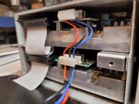
After more thorough testing and monitoring of the PSU this week, I deemed it a success without the need for any improvements or upgrades. All the voltages were stable, even the voltages going to the backplane. So, I got busy reassembling the PSU inside the case. I hate it when there's a screw left over. ;) I then proceeded to apply power to the mobo. My variac to the rescue, even though I knew the voltages were good. The mobo slowly came to life without any fanfare, or electrical mishaps. That was good.

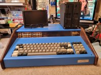
I plugged up a little LCD monitor I had from droning, and voila. I had the infamous carot > prompt. Wonders never cease! I issued a couple of the monitor commands and they seemed to work. Since I'm using Bob Hogg's DPM (Dual Personality Module), a few commands are different, and newer ones exist over the original plain vanilla Solos monitor. It was all good. Now I need a little composite-to-HDMI converter so I can use a bigger, modern display. I then plugged up power to the back-plane and added a 64K memory card, and a controller in. No sparks.

So success in little steps. The 45 yr old beast came back to life, without even a single spark, or whimper.

Next steps are to PC over to the Sol via a terminal access and transfer some images. Will also hopefully test a 51/4" drive using the VSG and see how that works in the coming days.

That's it for now...

Rick

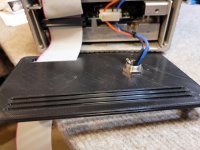
BTW, that little switch you can partially see hanging out over the front of the chassis on the right is a toggle for either an underline _ prompt, or a block prompt. I had forgotten what it did. I had it mounted on the metal keyboard cover part. I refurbished it a little and put some shrink-wrap on the connectors for a little strength and avoid any shorting.

Click image for larger version  Name:	20211015_082512.jpg Views:	0 Size:	155.0 KB ID:	1228589 Click image for larger version  Name:	20211015_082400.jpg Views:	0 Size:	167.4 KB ID:	1228590 Click image for larger version  Name:	20211015_082348.jpg Views:	0 Size:	186.1 KB ID:	1228591
 
Last edited:
Well done that man!

I think with your extended monitor it has a memory test routine. I would advise running the memory test routine on your memory just to needle out any 'iffy' RAM chips.

Perhaps you can now label the little switch - so that in 30 years time you will know what it does :)!

Dave
 
It's been a while, but I've had some good progress lately amidst the Sol serial demons. :) I finally got it and another PC talking together. Success! Better yet, I kept at it tonight earlier, and was able to get PC2FLOP executed and working. I transferred the Lifeboat CP/M 2.23a and was successful in writing the image to a disk. I was grinning big time when I restarted and executed E800 - NorthStar boot address and the screen came to life. It didn't exactly bring back a flood of memories, but it was nice to see it on the screen.

I have a lot to explore now, as I try and resurrect computing from 1981! Will write more later this week, but it was a good weekend in the vintage department. :) Pics aren't the best quality, but get the point across.

Rick

CPM-2.jpg CPM-3.jpg
 
It’s good when a plan comes together isn’t it :)!

Well done at sticking with it. I am helping someone else with serial transfer woes to get their machine up and running - so perhaps your post will give them some encouragement to stick with it.

Dave
 
daver2, Thanks for the help. As it turned out, most of time was spent on setting up and configuring the host computer for the serial port. I ended up having to update Windows then install an update, etc. Took too much time. Then next came the wiring of the two ended of my serial cable. I decided to use DB9/DB25 -to-RTJ45 connectors. This allow me to easily swap out the network cable for longer or shorter lengths if needed in the future. Now that I know my pin structure is working I can complete the DB connectors at each end. BTW, since I'm only using 3 pins for now, is there any benefit gained by connecting the DSR and DTR signals? Or, are most PL just using TX, RX and GND?

Also, with all the dynamic changes I was making yesterday, do the port setting for COM1 in Windows need to match those of TeraTerm and the Sol?

Rick

COM1 Port.jpg
 
Great work! Feels so good to finally “win” doesn’t it?

Mike

Great work Mike on the PC2FLOP and FLOP2PC programs. Those are great little utilities that allow for resurrecting and transferring data to a Sol - and back. I was soooo glad when after the transfer, and booted my disk the OS came to life. I have a lot to get reacquainted with! :)

BTW, I had to drop back to my original SOLOS prom to get this all working, only because of the way MicroComplex implemented the ENter command in the DPM (Dual Personality Module). Unless I'm wrong he only allowed 1-byt1 per line instead of multiple bytes. This rendered all of the .ENT files useless at least without a lot of manual parsing of the structure. I didn't feel inclined to do it. There's probably a way to automate the process. I guess he did that way to make manual data entry easier, as I don't believe the .ENT format was around at the time.

I just tested the DPM switched to F000 and it did not boot. Switching it back to C000, Lifeboat CP/M boot properly. All I had to do was press LOAD on the keyboard and the disk booted fine. Bobb H. (MicroCOmplex) claims that no mods to Lifeboat CP/M ) v2.21a are required to get a 60k of RAM system running. I have more to explore with that. Not sure why it did not boot using the DPM switched to F000. Like a patch needed somewhere in the LifeBoat boot process.

Anyway, all of this is good news and now I just need get reacquainted with CP/M commands and utilities. Back in the day I do remember have a copy of Life Boat (something), probably CP/M.

BTW, the 5.25" drive I ended up using was one that came out of my Slicer that just happened to be a DS/DD in like new condition. Now if I could only find another one. :)

That's the latest update.
 
BTW, the 5.25" drive I ended up using was one that came out of my Slicer that just happened to be a DS/DD in like new condition. Now if I could only find another one. :)

That's the latest update.

It is great having a pair of drives with the SOL, very convenient.

I put two drives in a box with a power supply and put Mike's VSG inside the box, powered by the psu in there. I used some new old stock Japanese made IBM brand DSDD YD-580 drives, they were not cheap, sealed in their boxes since the early 1980's but they are really beautiful stable direct drive types. I bought a few of them, very oddly one was defective from new and had a failed Hitachi 74 series logic IC in it, which I have never seen before, Hitachi brand 74 IC's IC's are normally super reliable. It prevented two drives working on the same cable, but the drive worked fine on its own and had me running around in circles for a while trying to figure it out !

https://www.worldphaco.com/uploads/EXTERNAL_DUAL_5.pdf
 
The floppy drive I found in my Slicer (that was packaged away as well), was a Mitsubishi, made in Japan model MF501A-312U. Fortunately, it was in near new condition and appears to be functioning fine. Upon closer inspection I found that it was DD/DS, so I was glad for that. It's a direct drive model as well, and appears to have a lot of electronics on it, and made really well. And it seems to work fine with my Micro Complex controller. But I only had one!. I knew that one drive is almost intolerable when it comes to copying files and entire disks, so I went looking for its twin. Fortunately, I found an identical model on 'fleabay', claiming to be NEW, but not in original packaging. Since the price was reasonable, I took a chance and ordered one. Hopefully, it will look and operate as new. :) So, I hope to have a dual-floppy system up and running in a few days. I did find an old..ish enclosure my son found at a local shoe store that was liquidating everything a few years back. We were going to throw it out, but never did. The case was designed for a single 5.25" drive, but sized big enough for two drives bays (sorta) once I removed the electronics. It had a CD-ROM and was part of a whole store music system. I'll have to a do a little DIY re-purposing for the 2nd drive to fit securely, and may 3D print new front and rear panels. There will be no room for an internal PSU, so I will use an external PSU brick. I did read your DIY project for 2-drives over the weekend. Came out great. Wish mine had room for the VSG, but it's just too tight.

I had forgotten about PCPUT and PCGET you had mentioned in another post, so will need to explore those commands. Yesterday, I printed out a CP/M 2.2 User Guide, to get myself re-acquainted with the OS. I also found an original Microsoft Basic 5 manual as well. Lots of brushing up to do. Actually, the Micro Complex owner (Bob Hogg) had written MC-DOS, to go along with his N* compatible 2D controller and the DPM. I found it on one of the vintage archive sites. Can't remember which one, since I've been visiting a lot of them lately. I've downloaded it, but have yet to try it out. I think it's a really a flavor of N* DOS with a few new commands.

Still lots to do and learn, but so far little bits are coming back. It's all fun.

Rick

DrvEnc_5.jpg DrvEnc_4.jpg DrvEnc_1.jpg DrvEnc_3.jpg DrvEnc_2.jpg
 
It's been a couple weeks from my last update, and will have more to share in a few days of my Sol progress. One question... Does anyone know the screw size for the 2, big knurled knobs used on the back of the Sol to hold the top cover in place? I've identified them in the parts list and hardware diagram X-10, but can't find the size specified anywhere. I'm sure there are newer and much better, suitable replacements available today, and was just curious if anyone had to replace theirs and what size they used. Mine got displaced at some point over the years(strangely?), so now I need a couple.

Rick

Knurled Knob.jpg
 
It's been a couple weeks from my last update, and will have more to share in a few days of my Sol progress. One question... Does anyone know the screw size for the 2, big knurled knobs used on the back of the Sol to hold the top cover in place? I've identified them in the parts list and hardware diagram X-10, but can't find the size specified anywhere. I'm sure there are newer and much better, suitable replacements available today, and was just curious if anyone had to replace theirs and what size they used. Mine got displaced at some point over the years(strangely?), so now I need a couple.

Rick

filedata/fetch?id=1232741&d=1637011177

Nice diagram.

When I first saw these screws on my Sol I thought, holy cow, what unusual screws. I have never seen these before on any other apparatus I own, nor seen them at any screw supplier including PSME in the USA. On mine I added a new nylon washer so they do not scratch the paint on the cover when they are done up. Hopefully somebody on the forum might recognize them and know a supplier.

You mentioned BASIC-5 in a post above. I like that program, so I put it in ROM's on a Bytesaver card. It was fun breaking it up into pieces. Then in the 7th ROM I put a Block move program that moves it down to its usual spot in low memory, leaving one spare ROM on the Bytesaver board for something else, I mentioned it here:

https://www.vcfed.org/forum/forum/genres/s-100/79917-bytesaver-block-move-program-basic-5

Most of the time though the BASIC I use on my SOL is MBASIC running in CP/M from a disk.
 
Last edited:
That illustration is actually straight out of the Sol manual, Section 6, page 4. I tried to do my homework before posting. ;) I'm sure I could figure out the size I need with a little trial and error and guestimation. I'm not likely to find any at my local Home Depot, or hardware store. eBay seems to have quite a selection to choose from, but on first search I didn't notice any with sheet metal type threads.

Here's another preview of some of my slooooooow progress. :) My 3D printer decided it needed some serious adjustments after a couple months of non use. So now it's sporting a new extruder assembly, and hotend. It only took me a couple days to get everything calibrated and my bed level! Now it's printing beautifully. If I could only get this ironing process sorted out, I'd have some smooth top surfaces.

FloppyFacePlate_1.jpg

It not perfect, but good enough for an old Sol, and an old soul like me. :) While the face plate was simple enough to create, getting everything spaced and aligned properly, especially the holes was challenging. It always seems simple at first! I won't disclose how many paper mock-ups and 3D trial print runs I went through to get to my stage of perfection.

Until the PC came along, I had always preferred vertical oriented floppy drives. Way back in the day, when I added 8" drives they were vertical, but my 2, 5.25" drives were horizontal in an external case IIRC. The enclosure shown above was re-purposed and is horizontal. Little rubber feet, or pads on the left side will allow either orientation wherever it finds a natural home in my man-cave - yet to be determined. Either way, it fits nicely on the top of the Sol. However, as I mentioned in an earlier post, there just wasn't any spare room inside to include the VSG, or include a proper power jack. However, I suppose I could install a 4-pin,round, low-voltage, DIN connector and make it all work. We'll see.

Hopefully, more pictures to come by end of week, or next week. Well, maybe not next week. My son will be home for a couple days over Thanksgiving, and we have a couple of new DACs that we want to have a 'shoot-out' with. We're both into audio too.

Rick
 
What you can do is on the rear panel of the unit you can attach a die cast box, that is a little smaller than the panel and does not obstruct the screw holes at the corners and put the VSG +/- any power supply you might need in that. It would make the overall unit simply a little longer.
 
It's been awhile since my last update. I realize my solution is very custom, so I'm not sure how much interest there is for detail, outside the few Sol followers here. Not too much interest I would guess in a dual-floppy system for a computer that's 45 years old! This has got to be the only forum that probably cares. :)

As mentioned in an earlier post, I repurposed a a perfectly sized enclosure that was destined for the trash bin until I rescued it. I had to make some mods to the internal aluminum structure to house the 2 half-height floppy drives. Fortunately, the aluminum was pretty thin and light so it was easy to work with. It was time consuming though. Next step was the front and rear panels. I decided to make them on my 3D printer instead of having them made professionally. The the front panel was designed in coordination with modifying the drive sub-structure. It took longer than expected to get the drives fitted properly and then design and 3D print the face plate.

Click image for larger version  Name:	20211120_094828.jpg Views:	0 Size:	138.4 KB ID:	1234160

I also had some 3D printing issues to resolve and that took extra time as well. But, after about 2 weeks, I finally had my printer adjusted well and laying down some good prints. For this project I used Front Panel Express (FPE) since I was familiar with it and the designs were fairly simple. All I had to do were a couple conversions from FPE files to STL files. Once I had the front one done I focused on the back. Each Panel was 171mm x 107mm x 4mm thick. 4mm is perfect if you need to mount jacks, or other things on it. Very sturdy, but takes a long time to print!

Click image for larger version  Name:	20211128_145856.jpg Views:	0 Size:	161.6 KB ID:	1234161

Since I was designing as I went along(often the case),I wasn't sure how I was going to get power to the drives. I was thinking at first I would simply use a y-styled Molex connector to a proper PSU. That led to an initial consideration of using a suitable Molex jack fitted on the back panel(see prototype sample).

Click image for larger version  Name:	20211120_094828.jpg Views:	0 Size:	138.4 KB ID:	1234160

I wasn't particularly fond of that solution, and as mentioned in my previous post, maybe a DIN jack would work better. There just wasn't enough spare room at the back of the enclosure to work with. Using a DIN jack turned out to be a good solution, because; (1) it was small enough to fit, and (2) the original power brick that came with enclosure, terminated to a 5-pin DIN plug, with the correct voltages. I re-did the 4-pin connectors going to the drives using RC silicone power wire. For a DIY'er there's nothing better than silicone. It supple, strong, and flexes for difficult locations. I use it almost exclusively now.

Click image for larger version  Name:	20211120_094828.jpg Views:	0 Size:	138.4 KB ID:	1234160 Click image for larger version  Name:	20211120_094828.jpg Views:	0 Size:	138.4 KB ID:	1234160 Click image for larger version  Name:	20211120_094828.jpg Views:	0 Size:	138.4 KB ID:	1234160 Click image for larger version  Name:	20211120_094828.jpg Views:	0 Size:	138.4 KB ID:	1234160

So, once my final rear panel was done and printed, I fitted the DIN jack to the drives 4-pin Molex connector cable. Ready for final testing. Everything worked as I expected and the 3D panels came out pretty nice looking. The only thing hanging out the back is the 34-pin floppy ribbon cable. That leads me to my OCB already thinking about version 2. To add additional items to the back panel.


Click image for larger version  Name:	20211120_094828.jpg Views:	0 Size:	138.4 KB ID:	1234160

With most of my other DIY builds, I always like to try and design a self-contained enclosure - with no attached cables hanging off the back. Except on occasion where an external power brick is used. And those are usually always removable too. For this 'first addition' of the project, I wanted to get it functional first, and then I would think about how to solve the secondary(perfection) items for the 2nd version. :) What I want to add is a, a proper IEC power jack with switch and fuse, and SMPS PSU. And possibly, room for the VSG along with a detachable jack for the 34-pin ribbon cable. So this project will likely have a sequel. But that won't happen until next year and be the topic for another thread. Is any of that necessary? No, but it's just my preferred long-term solution.

Now that I have a working, 2-drive NorthStar CP/M system up and running I'll be able to focus on the transferring software/apps, and writing images to disks. There's a lot to explore there. So that's my next challenge. Getting Basic, Electric Pencil, Wordstar and a few others installed and working.

Click image for larger version  Name:	20211128_151812.jpg Views:	0 Size:	171.9 KB ID:	1234164 Click image for larger version  Name:	20211128_151812.jpg Views:	0 Size:	171.9 KB ID:	1234164

Anyway, the journey continues. Some things are coming back a bit, as I've been looking over the CP/M user guide and other docs I've downloaded.

Rick
 

Attachments

  • 20211128_130042.jpg
    20211128_130042.jpg
    160.8 KB · Views: 1
  • 20211128_130629.jpg
    20211128_130629.jpg
    139.4 KB · Views: 1
  • 20211128_152317.jpg
    20211128_152317.jpg
    180.1 KB · Views: 1
Very nice looking floppy enclosure. Good luck running CP/M software that should be a lot of fun. I have a dual 5 1/4 drive from DEC that was once used with a TRS-80 Color Computer. Unfortunately all of my CP/M software is on 8in Disks so I will have to check out PC2FLOP like you mentioned. It is nice to see your progress, my set of foam and foil from TexElec just came in, so hopefully those will do the trick, my Sun Type 4 Keys were just not thick enough, worse case scenario I will glue this set onto the others. I am also in the process of building an Altair 8800c, so I might be posting about that in the coming months.
 
Speaking of PC2FLOP.... Now I'm entering the, 'how much can I remember phase' about N* DOS and CP/M having been decades! So far, it's apparently not much. :) I've got PC2FLOP at least executing on the Sol, with it's simple menu options. I spent time transferring a couple images, first at 1200 baud and then at 9600 baud. I chose Transfer and XMoDem. The TeraTerm xfer window opened and displayed the standard progress bar, while the data was sent to the Sol. I could hear and see activity on the drive when it was presumably writing information to the disk. Obviously, I'm using Mike's VSG dongle. Great little piece of hardware!

I say presumably because after attempting 4 different images (all .NSI), when I went to look at the contents of the disk 4 disks, nothing was there.:( I'll admit I'm flying a little blind here, since I am trying to absorb a lot of information, files, formats, etc. that I have no reference point for what I should be seeing on these disk. I'm pretty sure they should not be blank. I'm searching, and going back over docs and threads, as this is probably the best place to pose these questions and issues. So, given those symptoms, it seems like data is being written to the disk, yet the disk comes up empty - or at the very least cannot display any of the files.

Ok, while checking my facts in this post, I just came across something that needs clarification and may be the root of my empty disks. Question is.... are images created using Dave Dunfield's utility able to be read and used with PC2FLOP? What issues should I be aware of going forward, so I'm not needlessly spinning my wheels because I'm doing it backasswards!

At this point I'm just trying to get this transfer and writing to a disk process figured out. I have other questions, but for now I'll leave at this point.

Thanks in advance for sharing your time, patience and expert knowledge.
 
Very nice looking floppy enclosure. Good luck running CP/M software that should be a lot of fun. I have a dual 5 1/4 drive from DEC that was once used with a TRS-80 Color Computer. Unfortunately all of my CP/M software is on 8in Disks so I will have to check out PC2FLOP like you mentioned. It is nice to see your progress, my set of foam and foil from TexElec just came in, so hopefully those will do the trick, my Sun Type 4 Keys were just not thick enough, worse case scenario I will glue this set onto the others. I am also in the process of building an Altair 8800c, so I might be posting about that in the coming months.

Thanks boxer. It ended up being a lot more work than originally thought. Seems like that is always the case. I'm pretty pleased with how it came out and it should provide me - for what I need - an essential tool, as I re-explore the Sol and some very, very dated old software.
 
I see now that DD's ImageDisk works with .IMD files (only?) I have not attempted using ID yet. Still exploring what will work with what I have operational at this point.
 
Can someone point me to a correct image of N* DOS already configured with the proper I/O patched for the Sol where I could download it? I'm having a lot of trouble writing any of the DD N* image to a disk that will then boot.

To SAVE PC2FLOP in memory to my CP/M boot disk, what are the correct # of pages(256-byte blocks) to use with the SAVE command? Sorry for all these newbie questions.

The syntax is, SAVE #p file-name
 
Back
Top