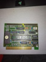
A few weeks ago i found a PC XT hard drive set..
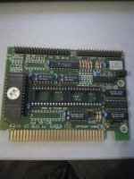
It came with an very rare PC XT-IDE controller interface card and a super FDC controller on one controller board..
For archive purpose i had to backup the onboard rom (before using this board) Which i did..
I dont have any manual for it, and also the FDC part doesnt seems to work strangely..
I also had to look in the bios rom to see if there was anything mentioned by manufacturer or other important clues which could help to clearify who made this pcb controller board and how to know to set it up..
I had some problems with the included seagate ST 325x hard drive it came with.. It didnt spin on could boot.. So i had to lift the controllerboard by hand and also free-ed up the engine by rotate it both sides..
After i did this. I mounted the controller board back and the drive spon up again (came back to live)
And connector the 40 pin ide cable to it and the drive booted up till the C: prompt..
For all i could see in the rom that something says `al corp`
Does anybody knows what the jumper setting are for (only know that there is a jumper for 27c64 and 27c128 roms and that there is a way to set the roms addres..
I like to know how to set up the floppy drive types.. (it seems it cant set it normally like with the regular jumper block.)
Anyone know what HDC jumper is for> i guess its for enable and disable the harddrive part. Ive already put a jumper on in horizontal position, but that seems to do anything..
What is DGSEL for?? (SEL should stand for `select`i guess)
Attachments
Last edited:
 The board does not have to be disassembled, it can be just left as is.
