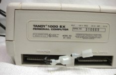
I have 3 Tandy external disk drives. I believe I could use these with my Tandy HX computer (one 3.5" and two 5.25"). I got these in a lot of other stuff and the cables were not included. They have a small plug next to the card edge where you would attach the cable. How did these hook up to the computer? Did they have an external power source or get power from the computer? Can I get the cables anywhere?
Upcoming Events:
- VCF South West - June 14 - 16, Davidson-Gundy Alumni Center at University of Texas at Dallas
- VCF West - Aug 2 - 3, Computer History Museum, Mountain View, CA
- VCF Midwest - Sept 7 - 8 2024, Schaumburg, IL
- VCF SoCal - Mid February 2025, Location TBD, Southern CA
- VCF East - April 2025, Infoage Museum, Wall NJ
-
Please review our updated Terms and Rules here
You are using an out of date browser. It may not display this or other websites correctly.
You should upgrade or use an alternative browser.
You should upgrade or use an alternative browser.
Tandy External Disk Drive help
- Thread starter Gribnitz
- Start date
TRS-Ian
Veteran Member
What are the catalog numbers of the three external drives?
With the numbers I can help ascertain the suitability of these drives for MS-DOS application.
Ian.
With the numbers I can help ascertain the suitability of these drives for MS-DOS application.
Ian.
dJOS
Veteran Member
What are the catalog numbers of the three external drives?
Doh, I didn't even think to check that catalog number. They are 25-1061 for the 3.5" drive and 25-1060B for the 5.25" drive. Can I still find the ribbon cables for these somewhere?
Thanks!
Last edited:
dJOS
Veteran Member
Doh, I didn't even think to check that catalog number. They are 25-1061 for the 3.5" drive and 25-1060B for the 5.25" drive. Can I still find the ribbon cables for these somewhere?
Thanks!
You can't even buy 30 pin edge connector with IDC termination anymore, I've been looking for weeks!
I've managed to find some 30 pin edge connector's designed for through hole PCB mounting so I'm just going to solder them direct to the ribbon cable.
If I'm successful making one for myself, I'd be happy to make you one if you like?
I've managed to find some 30 pin edge connector's designed for through hole PCB mounting so I'm just going to solder them direct to the ribbon cable.
If I'm successful making one for myself, I'd be happy to make you one if you like?
That would be fantastic! I love this Tandy HX, but most of my software is 5.25". I have found the 3.5" disks seem to go bad a lot faster than 5.25" as well. Please let me know if you get them to work!
dJOS
Veteran Member
That would be fantastic! I love this Tandy HX, but most of my software is 5.25". I have found the 3.5" disks seem to go bad a lot faster than 5.25" as well. Please let me know if you get them to work!
No worries, I have about 10 connectors coming so I can easily make more cables if they work. I'm hoping they are here by the end of the month and I'll report back in this topic.
ldkraemer
Veteran Member
dJOS,
Why can't you use a standard 34 Pin Edge Card Connector with a bit of the plastic milled off each end so it goes into the slot in the case.
You could even insert two of the keying devices in the connector so it fits nicely on the 30 Pin connector. It shouldn't take long to mill
a bit off each end to get things to fit properly.
Another option would be to get some of the long tail headers from:
http://www.king-cart.com/phoenixent/category=HEADERS+BREAKAWAY+.1SP+STR
Part Number = HWS3835
2x20 Header .1sp Long Tails .340 .230
and push them into a standard Socket connector, then cut the long ends so they could be soldered to the existing
circuit board on both sides. The Socket Connectors are also 34 Pin.
Larry
dJOS
Veteran Member
dJOS,
Why can't you use a standard 34 Pin Edge Card Connector with a bit of the plastic milled off each end so it goes into the slot in the case.
You could even insert two of the keying devices in the connector so it fits nicely on the 30 Pin connector. It shouldn't take long to mill
a bit off each end to get things to fit properly.
Another option would be to get some of the long tail headers from:
http://www.king-cart.com/phoenixent/category=HEADERS+BREAKAWAY+.1SP+STR
Part Number = HWS3835
2x20 Header .1sp Long Tails .340 .230
and push them into a standard Socket connector, then cut the long ends so they could be soldered to the existing
circuit board on both sides. The Socket Connectors are also 34 Pin.
Larry
That's an option but imo it'd be ugly, at least with the connectors I've bought, I can shrink tube over the soldering so it'll look decent. I also don't want to Frankenstein my 1000ex either by soldering header pins onto the edge connector.
ldkraemer
Veteran Member
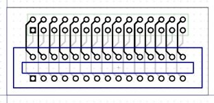
Since you have located "30 pin edge connector's designed for through hole PCB mounting", why don't you create a small circuit board
with EASYEDA. You just need two connectors, the 30 Pin Card Edge Connector, and a 30 Pin DIP Header (15x2). It shouldn't take
long for your PCB's to be delivered. Plus, others would benefit from your PCB.
UPDATE:
The following Adapter will allow you to use a 30 Pin Edge Card Solder Tail Connector and a 30 Pin DIP Male Header.
Both of which should be easy to locate.
Go to EASYEDA, the Search for the following Public File: 30 Edge Connector
https://easyeda.com/ldkraemer/30_Edge_Connector-5d5728afc69d41e6b66a55131945faa0
Larry
Last edited:
dJOS
Veteran Member
Since you have located "30 pin edge connector's designed for through hole PCB mounting", why don't you create a small circuit board
with EASYEDA. You just need two connectors, the 30 Pin Card Edge Connector, and a 30 Pin DIP Header (15x2). It shouldn't take
long for your PCB's to be delivered. Plus, others would benefit from your PCB.
UPDATE:
The following Adapter will allow you to use a 30 Pin Edge Card Solder Tail Connector and a 30 Pin DIP Male Header.
Both of which should be easy to locate.
Go to EASYEDA, the Search for the following Public File: 30 Edge Connector
https://easyeda.com/ldkraemer/30_Edge_Connector-5d5728afc69d41e6b66a55131945faa0
Larry
Hmmm, that's actually a pretty good idea. I'll look into it.
ldkraemer
Veteran Member
If you open the PCB file, there is a menu button "FABRICATE OUTPUT"at the top where you can place an order for the boards.
Six or eight boards, plus postage shouldn't be that much.
You better double check the wiring from, some pins like Pin 2 & 30 through to the Edge Connector. I believe it is correct,
but another set of eyes on it won't hurt.
EASYEDA will ship the PCB's, and you should have them in around 2 1/2 weeks, or at least other boards I've ordered come
in that amount of time. They will be nice looking PCB's.
Larry
dJOS
Veteran Member
If you open the PCB file, there is a menu button "FABRICATE OUTPUT"at the top where you can place an order for the boards.
Six or eight boards, plus postage shouldn't be that much.
You better double check the wiring from, some pins like Pin 2 & 30 through to the Edge Connector. I believe it is correct,
but another set of eyes on it won't hurt.
EASYEDA will ship the PCB's, and you should have them in around 2 1/2 weeks, or at least other boards I've ordered come
in that amount of time. They will be nice looking PCB's.
Larry
I have eagle for PCB designs so the design etc isn't an issue.
dJOS
Veteran Member
If you open the PCB file, there is a menu button "FABRICATE OUTPUT"at the top where you can place an order for the boards.
Six or eight boards, plus postage shouldn't be that much.
You better double check the wiring from, some pins like Pin 2 & 30 through to the Edge Connector. I believe it is correct,
but another set of eyes on it won't hurt.
EASYEDA will ship the PCB's, and you should have them in around 2 1/2 weeks, or at least other boards I've ordered come
in that amount of time. They will be nice looking PCB's.
Larry
Neat little design, wiring looks ok to me too.
However I'll wait till my Edge connectors arrive so I can confirm the pin arrangement is the same as regular 2.54mm Male pin headers (I dont believe the Row spacing is the same) - Also I think a bit more room might be required for the foot print of the Edge Connector.
i!1BO139wf9Qg~~/s-l1600.jpg)
dJOS
Veteran Member
ldkraemer
Veteran Member
I'm curious what you used for the following (in mils):
1. Trace Width =
2. Hole Diameter =
3. Pad Diameter =
Thanks.
Larry
1. Trace Width =
2. Hole Diameter =
3. Pad Diameter =
Thanks.
Larry
dJOS
Veteran Member
I'm curious what you used for the following (in mils):
1. Trace Width =
2. Hole Diameter =
3. Pad Diameter =
Thanks.
Larry
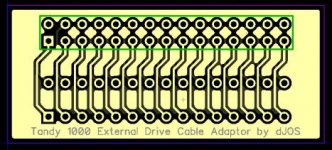
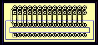
I used the defaults for everything, but both parts were using standard 2.54 mm distance between hole centre's with standard pin sizes.
1. Trace Width = .33 mm
2. Hole Diameter = 1 mm
3. Pad Diameter = 1.5 mm
Last edited:
dJOS
Veteran Member
dJOS
Veteran Member
Just ordered 10 boards from Elecrow in Blue - hopefully the boards work fine, I've never used Elecrow before.


