• Please review our updated Terms and Rules here

Tape issue on IBM 5110 Type 1

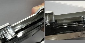
I was thinking about the note of the head possibly being tilted.

The bracket that the black grounding wire attaches to is "sunk" into the plastic, giving a fairly sturdy base (and a level surface). It may be hard to visualize the image below without being familiar with the tape deck arrangement - but the image is with the tape-drive PCB logic board removed.


electro_mag.jpg


It occurred to me that if that black ground wire was loose, perhaps the other wires behind the head might also be loose? (especially since I think they are supposed to be tucked in behind that enclosure, not to the side). So I took the metal shroud off (since I think in reviewing the 5100 MIM, it didn't show having that shroud enclosure around the head - the Edwin Starr song "what is it good for, absolutely nothin'" came to mind). I buttoned everything back together (sans shroud), but still same 003 E80 error result during MARK. (and the cables behind this electro-mag all seemed secured).


electr_mag2.jpg


I also took the Common/Language ROS from the 5110 Type2 (type2's don't have internal tape drive) and placed it in the Type1, to see if it would respond to tape commands - and it does! Same results (REWIND works, MARK rewinds to the single dot mark then gives an 003 error), but the fact that tape commands are responding at all gives me hope that a tape unit could be retrofitted into a 5110 Type2.
 
I guess it probably won't be anything as easy as head alignment, unfortunately. And that blue sticker with "24256" on it doesn't looked kinked as it would if the head got moved as much as I thought it might have.

It's probably time to start focusing on the electronics. Eliminate easy stuff first --- does everything look plugged in/well-connected?

Tape heads are a lot like transformers: they have minuscule coils of fine wire inside. If one of the wires breaks within the head, then it can't really be repaired. Is it possible to unplug the tape head from the rest of the drive and check continuity across the head? It won't be zero ohms, but if it's infinity, there's a problem!

(Don't forget that the tape head is actually several heads all in the same package, so there are probably multiple wire pairs to test.)
 
Ok, as expected the IBM tape had the same result as the 3M ones. But I will say the IBM tape material has more "crisp" edges. I can't say for sure how old this IBM tape is, but the 3M tapes were possibly from around 1994 (and the edges of the tape material on those look intact, but are a little "wavy" on the sides/edges, unlike the IBM one that is more straight/taut -- they both came from unopened packages).

So, we're going in! Since that ground wire was loose, I suspect "someone's been inside here before!" So, what else might be loose inside? Well, turns one, one of the bolts of the belt motor was loose - while I never heard/noticed any excessive noise while the tape was in motion, that motor did "tilt" slightly. The bolt was wedges below the keyboard - so it's back where it belongs. As bad it sounds, I don't think it was really the cause of any issues (it may have eventually worn the belt out sooner or caused some issues long term, but I don't think it was the cause of the immediate read/write issue I'm having -- since it was secured by 3 other bolts once mounted in the main case).

Also, the manual makes a pretty big deal out of these "locking wheel assembly" - "all locking wheels must be adjusted properly to prevent slippage between the capstan and spindle." And, I think I'm missing the two back wheels? Or are they suppose to be clear spools like that? (see below) The extra slight pressure of those back wheels may be what help secure the tape in place on its own. But dropping those rear wheel locks back out is a big pain (lots of un-bolting to get to them).

IMG_1998A.jpgIMG_2006A.jpg


The MIM also makes a big deal about this washer (highlighted below): "The jackshaft housing is positioned at the factory using the stop washer as a reference." (i.e. it applies some pressure to keep the jackshaft housing centered). Also, just for reference is the label on the main drive motor.

IMG_2007A.jpg

More soon...
 
Last edited:
So, I don't fully understand how the magnets works to turn the tape cartridge. But since my tape is moving (then hits the "two dots" then fast forward back to the "single dot" BOT marker) in both directions, I think the belt, spindle, and magnets are all adjusted ok (another reason I wasn't too worried about the missing mounting bolt area on the drive motor, but glad it was found):

IMG_2012A.jpg


Any brief explanation? in the above image, there are two wires going into near the magnets and fwd/reverse jackshaft rolls. I'm not sure how to tell if these are plugged in correctly (or than presumably the tape is being moved forward and backwards correctly as commanded, so I'll leave these two yellow wires alone). Still, the drive motor (I think) goes forward or reverse and with a belt, so it turns these jackshaft rolls (I guess with power from these two yellow cables). These jackshaft rolls aren't directly connected to the spindle (and the spindle seems to be a rubber sleeve material over a metal shaft) -- so, what are the select-magnets for? (the MIM also describes adjustment procedures for those select magnets, on both sides) Why isn't the drive belt itself sufficient?
 
Last edited:
Then regarding the head itself -- how do I know which way the 4-pin and 6-pin wiring goes? It was probably correct in the way it was set (from earlier photos), but not sure how to confirm that -- and not sure what the risk of just plugging it in reverse (to see if that original order was backwards)?

But before gambling on that, I have a message out to http://www.jrfmagnetics.com/ who seems to be familiar with these Nortronic heads. Hopefully can find a pin out (or even better, a substitute/replacement!)

In the 6-pin side, I have continuity between 3 of those pins (will double check tomorrow) - not sure what else to check about the pins.

IMG_2017A.jpgIMG_2016A.jpg
 
Wow, when you go in, you really go in. I'm grateful for these pictures; I've never disassembled my 5100's tape drive this far, and it's handy to see what I might expect to find :)

Talking through some of your points (although I can't help with a lot of them; you're in new territory for me!)

Wavy tape: Betcha it'd go away after a few rounds of retensioning (winding it all the way from one end to the other).

Locking wheels: Those are them, and I think there may be some on top, too. I think they're supposed to have a rubber "tire" on the outside that has mostly disappeared on your tape drive and on mine. You could try bulking them up with a thin strip of electrical tape or something, just to see if it works...

Belt, spindle and magnets: I agree, they're all probably fine. It's very nice to see such good pictures of them!

How the tape motion mechanism works: Here's the thing --- whenever the computer is on, the motor is always turning, and so are both jackshafts. The jackshaft-spindle-select magnet mechanism is a clutch. Most of the time, neither jackshaft is touching the spindle (as you note), but when the tape drive wants to move the tape forward, the forward select magnet puts the forward drive jackshaft in contact with the spindle, which starts the spindle turning. When it wants to go backward, it's the same with the reverse select magnet.

Tape head wiring: I don't know how it goes, unfortunately. Let's wait on JRF Magnetics to (hopefully) get an answer about the head's pinout.

Nortronics: This is an interesting discovery! The PDFs on the JRF Magnetics website are interesting to browse. Since you have the head removed from the machine (and I hope it's not too hard to put it back!), consider measuring some of its dimensions and comparing them to the heads shown in this PDF, especially "5B 6000/PA2Q" and "24B 6100/PA2H". Those two are examples of the "PREMIUM 2-Track Stereo COMBO" heads found in this PDF. They look very similar, although whether they are internally compatible with the tape drive's own head is unclear.

Bonus: If the screw-secured cover that says "LINE TO 300 VOLTS" lifts away easily, I'd be curious to see any markings on the capacitor that lies beneath it... Feel free to refuse, after all I have one just like it in my own computer.
 
Ah, that explains the tread and black residue on the jackshaft rolls (worn material from the spindle). And it didn't occur to me about the belt rolling all the time - thanks, all that makes sense now! So, the belt itself never changes direction, right?

I'd like to see them in motion (with one of the rolls "selected"), I'll think about a way to record that (possibly with the keyboard removed, or the tape unit "half way" out of the system -- you can run the system with the A1 board flipped out, gives some bay room to work with).

No response from JRF Magnetics yet, but we're going into a holiday weekend. May take some time. Meanwhile, yep, I'll take some measurements and probe pins. I wonder, would one of those scan machines at an airport be able to see inside this head? (they can see thru certain metal enclosures). Would love to see inside without actually any cutting.

EDIT: Installing/removing the head is easy (well, once the tape control card PCB is out of the way - which is also easy, but just be gentle). The only specific thing the MIM states for adjusting the head is "Move read/write head as far forward and as far to the left as possible" (implied as within the slot assigned for it to be in -- and I assume by left, it means our left when facing the system, as if preparing to insert a cassette). And by forward, I assume it means "towards you" -- forwards towards the front of the system.
 
Last edited:
Here are my measurements of the Nortronics head for the IBM 5110 tape unit. On the back-left it has 4 thicker pins, on the back-right it has 6 "normal" pins. I saw no continuity between any of the pins on the back-left side (or of the metal enclosure/shell/housing itself). On the right-back side, I measured continuity as shown below (between the "lower right" 3 pins and the "upper left" 3 pins:


1653519649685.png


I've measured the +5v / +12v, and -5v / -12v across both the "tape unit cable" (from the A1 board) and the "internal cable" (the pin at the other end of the tape unit PCB), and all those checked out ok (voltage-measurements-wise).

I assume the head must be involved with the internal cable pins highlighted above. I guess with the connectors partially connected, I may be able to check continuity back through the internal cable - I may try that tomorrow.
 
Here is the requested "label" on tape deck capacitor. Yep, just remove that 1 screw and the bracket pivots out gently. There was no sticker label below the metal bracket, but the capacitor lifts out and the wires are long enough to turn it around enough to see the stamp on the other side. The number on the bottom of that capacitor is "736" (stamped in black) if that means anything.

IMG_2021A_small.jpg
 

Attachments

  • IMG_2024A_small.jpg
    IMG_2024A_small.jpg
    180 KB · Views: 2
Couldn't resist, went ahead and tested continuity between each of the head pins (while plugged in, using the original "as-obtained" orientation of the plugs -- which is probably right, but still TBD on verifying if that is correct or reversed/inverted from what it should be). So here is an updated chart....

1653552447468.png

So... Still not sure about the B09/D09 pins ("Raw Data (read data)"). I assume that's the job of the tape control card PCB - to interpret B04-B06/D04-D06 CH0 and CH1 signals, and convert that into "raw data" and send it out on B09/D09 ? But still not clear how "writes" work (is the label on B09 or D09 wrong, and it actually means "Raw Data (write data)" on one of them)?

And to clarify, yes - for the pin I marked as #1 (top left on the 6-pin side), it has continuity with all three of D04 and D05 and D06 (similarly for pins 2, 4 and the pins 3-6 have continuity with B04, B05, B06).

Hopefully will get time to explore the JRF PDFs tomorrow.
 
B09/D09 both being read data lines fits. The B pins are connected to Channel 0 (the upper read head) and the D pins are connected to Channel 1. I could be wrong but the writes might entail directly enabling the + and - coil lines to get the needed flux transitions.
 
Makes sense (read for B and read for D). And to be sure - it's not like interlaced data, the same data is written to both the lower/upper in parallel, built-in redundancy for accuracy? (I think I recall the later Commodore and TRS-80 tapes using that same convention)

What's the difference between B08 and D08? I ask since typically all GND have continuity to each other, and these two don't (I'll double check on that tonight).
 
I think it's not the case that the same data is written to upper/lower in parallel, depending on what you mean --- or at least that's not the case for the 5100. One track is used for format information, the other is used for data information. See PDF pages 231-233 in the 5100 MIM.

Thanks for having a look at the capacitor. While it is an oil-filled cap from the '70s, the good news is that it seems Sprague's ECCOL line was free of PCBs. Who knows if the capacitor in the AC box under your monitor is the same, but it would be nice if it were.

You are correct that the belt only turns one way. It also can only ever turn one speed, since the motor is an AC synchronous motor --- it's determined by the line frequency of your mains power. (This is why I said earlier that there is no "fast forward" or "fast rewind".) Since my 5100 is a 60 Hz machine and the UK uses 50 Hz power, I have to go to some trouble to achieve the line frequency that my computer needs.

The +coil/centre tap/-coil arrangement is not surprising --- remember how I mentioned something like how a tape head is a bit like half of a transformer. In this case, our tape head is a bit like half of a centre-tapped transformer.

Your puzzle about the raw read data lines is interesting. I think @krebizfan is probably correct. When reading, the heads only "detect" (that is, generate voltage) when the magnetic signal on the tape changes (that is, when it encounters a boundary between a region of tape magnetised N-S and a region of tape magnetised S-N). But when writing, the tape heads have to magnetise the whole region. Put differently, reads happen at the edges of regions; writes involve "painting" entire regions. It makes sense that they might use different mechanisms!

My hypothesis for the B08/D08 mystery is this: they will be common when the cable is plugged in, but otherwise they remain disconnected. I notice that D08 is noted as being the cable shield, and there are some applications where you only want to connect the cable shield to ground at one end of the cable. (Try a Google search on "cable shield both ends" to see people arguing online about it.) Perhaps this is one of those one-side-only applications.

Please do take a look at those JRF PDFs :) . They are all short, just one page each. If you measure the features on the front of your tape head and find that they are in the same locations as the features on some of the tape heads in the diagrams, then we may be one step closer to finding a replacement tape head for 5100 and 5110 tape drives.
 
Thanks for the clarifications! I used tape decks in the early 80s, but never looked very deep into how they operated. Many folks considered them hopelessly unreliable, but I never had much trouble with them - just write down your indexes. Of course there is no tape counter index on the 5110, but instead uniform-sized file indexes. I know in modern data formats there are Allocation Units - like 16386 bytes might be a typical unit. So each file, even if it is only 1 byte, still consumes a full allocation unit of 16KB. It's neat to see how the lineage of that goes all the way back to these early systems (i.e. if you MARK your files as max size 5K, then your small 100 byte program is still going to be placed into a 5K file index unit).


An update on the B08/D08 ground.... @stepleton is correct, when the take deck control PCB is inserted back into place, these two pins then have continuity. Cool :)


Speaking of the PCB, time to examine that more closely... Offhand nothing stands out to me as out of place in this PCB.

IMG_2054B.jpg

The Z2 to A1 connector ("top left" in the image above) has these pins (which many things are just pass-thru to the tape cable at the other end, but there is a READ CLOCK mentioned on this side, and the WRITE DATA is command from this side)...
1653618499001.png


I'm rusty on diode testing, but with the black diode as an example below (right center)....

The top number is "350" and I think the bottom number is "483" (or 453). Here are test results doing the Diode and Resistance test:

RED (left) BLACK (right) 1.589V ~12 Mohm
BLACK (left) RED (right) 0.714V ~23 Mohm (i.e. with leads reserved, here are the Diode and Resistance test results)

No OL condition and not getting same value after swapping leads - is that evidence enough that this diode is probably OK ?

5110_Tape_diode.jpg


As a reminder, we're trying to determine here why a MARK 3,2,1 command is returning 003 E80 error. The drive is responding to REWIND commands (I can manually roll the tape forward, then it rewinds to the double-hole marker, then forward back to the BOT single-dot marker on the tape).


Another thought on flipping/reversing the pins on the head: reversing the 6-pin connector doesn't seem to really be harmful - it would just read/write the channels backwards? (which actually if always using the same tape, does it matter which side of the tape has which channel?) However, if the 4-pin connector got reversed (connected "up-side-down"), I'm not sure how bad that would be - would it just be trying to erase all the time if a constant 5V was put on those erase channel 1/0 pins? Or might it quickly or eventually damage that erase side components?
 
Last edited:
Are you certain that the black component is a diode? Usually diodes have a band that marks the cathode, and I don't see one there.

Debugging this PCB will be a challenge, if indeed this is where the problem lies. Here are things that make it hard:

- We don't have a schematic (you could reverse-engineer one with your continuity tester...)
- Some parts will be IBM proprietary (those famous SLT/MST square cans in particular)
- Many others may be commodity parts but may have IBM-specific part numbers (e.g. 2392100 instead of 7400 for a TTL IC)

You can try to find some information out there. The 361431 can apparently contains "eight single diodes"; for the other can packages I had little luck finding anything. For the IBM part numbers on the DIPs, your Googling might turn up partial references like this one --- good luck!

For further understanding of the PCB, you will just have to use your noodle. Consider facts like the following:

- There are two read/write heads, therefore if you see twins on the board (like those two 8-pin DIPs), maybe they're for the heads
- But wait, there are also two select magnets...
- Signals coming from the tape are pretty small, so they need amplification
- Electromagnets are current-hungry --- they need beefier components
- Electromagnets are also inductive loads: be on the lookout for parts of the circuit that are snubbers
- At least you have the cable pinouts as a guide to what the external parts of the circuit are doing

I think we talked in another thread about whether you had an oscilloscope or not. Would it make sense to put it on some of the lines while the machine is running and check whether (for example) +Tape Clock ever has anything like a clock signal on it? We don't know when it's supposed to have a clock or what the clock will look like, but if it never looks like a clock, that might be a clue...
 
Are you certain that the black component is a diode?

Not at all :D All good points about the PCB. And I didn't have an o-scope until a couple days ago!! Good ones are expensive, but I think I found one that will suite the needs here. But before pursuing the PCB further, I'll wait for JRF to weigh in. I think I can remove the head from the bracket -- I think it is two extremely-tiny set screws (probably one behind the blue tape), so I could ship the head for an examination if that option came available.

Looking thru the PDFs, you're right -- P-A2Q/A2Q or P-A2H/A2H look close (I think the A2H is a larger version). Still not sure about its pinout -- from the diagram below, I see the 6-pins, but no equivalent to the 4-pin that was the erase side of the original IBM head.

1653715057573.png


With the o-scope now, I may switch focus on the keyboard project. Having the functional tape unit would be great, to save some experimental work and be able to resume (reload) the work later. But with a functional keyboard interface - we could essentially "save work" by storing it externally, and just "automatically" re-typing it (scripted input, that can work for both DCP machine code and BASIC/APL code). And with DCP machine code - I'm curious what kind of "graphic demos" might become possible with direct screen access.
 
Sounds good, looking forward to seeing how you get on. The tape drive is good fun but probably not the storage medium of choice if you have other options. I'd be happy to keep debugging from afar later if you pick it up again. The scope you have will probably be adequate.

Unfortunately the wiring diagram for the head there indicates that the A2Q probably isn't a good fit, even accounting for the different pin locations. It looks like each of the read/write and erase heads has a single coil with two connectors. What we need is each read/write head to have three pins (two on each end of the head's coil and one attached to its centre). The erase head pins appear to me to be fine.

That said, given the continuity you were able to measure between the pins in your own tape head, I think yours is likely to be OK.

The DCP program I'd like to write is a Forth interpreter, giving the 5100 another programming language. Of course, the 5100/5110 way to do it is never to run the interpreter on the PALM itself, but instead to have the PALM emulate another architecture and then run the interpreter on top of that. The RCA 1802 is a suitably quirky choice that also has some parallels with PALM, like 16 registers and an 8-bit ALU...
 
Last edited:
For reference, here is a sample of the "internals" of the internal IBM 5110 tape unit (including powered up and in-action):


And I agree, I have a feeling the tape head is fine. But now understanding the belt better, I realize this means that the data is read/written at this same constant speed as well. That seems inefficient, but I suppose it is a compromise to access speed.

These tapes are ultimately only going to last so long (the tape medium itself), and mechanical parts that move will wear out (the spindle itself seems to have a limited life, if it's literally worn away during use). So there is still a long term goal of having a tape-emulator (it could slide right onto the tape-control pins, and users could unplug the tape unit power -- i.e. the larger plugs that just powers the belt and tape-unit fan, since a small digital emulator wouldn't need any of that).


Regarding the "DCP program", just to clarify to others who may be reading in the future: the 5100/5110's have a built in DCP (diagnostic control program) accessible either during startup, or a slightly different key combination during normal usage. In there is an option to access a very primitive "assembler" - it is actually just a direct "machine language" insert at a specific RWS address (I tend to still call an assembler just because in my head assembler mnemonics are just an alternative syntax of machine code, but I recognize that a true assembler is much more then that). Anyhow, you don't really program in "DCP" -- you use the DCP to access a feature that lets you specify PALM machine code instructions (which is akin to flipping switches on an Altair 8080 to store instructions at specific addresses). The only "assembler" feature of the DCP input is that it shows the address on the CRT, and allows you to specify inputs in hex instead of raw binary (as the Altair switches were), it doesn't do any PALM mnemonic translation.

As far as alternative ways to load/store data into this system -- conceptually we could prepare a very small PALM machine code sequence that should be able to bit-bang bytes in/out of the back-side external ports (i.e. initial a portion of RWS based on received content on the external pins). The base hardware to support that should be available on all variants, but then there is the issue of how to load-this-loader in the first place (which wasn't that essentially Paul Allen's issue on their flight over to MITS? hand crafting a set of instructions to get their BASIC interpreter loaded?) It'll be a pain to have to key that in during each startup of the system - hence either having the "keyboard-auto-typer" available, or a working tape unit (or emulated one).
 
Another possibility comes to mind:

1653862123103.png


The H2 base I/O card is the one next to the Processor (linked together by some cross-bridge as they are inserted together). There is another I/O card in the A-slot, but that is for the external pins at the back of the entire unit.


I have two other Base I/O cards. However, they are from Type 2 5110's that normally don't have tape drive units. I tried them both, with an interesting result:

- By default, the swapped base I/O cards defaulted to D80 (makes sense, the Type 2's are normally intended for use with a disk drive unit). I've read somewhere there is a command that can be issued to change this default to another device. But in any case, you can override the default device in the commands themselves. i.e. REWIND E80 explicitly means the first tape drive unit. But assuming the PALM Processor card is identical across the ones I have, it's interesting the Base I/O has this much influence.


- When issuing REWIND E80, I get error 013 - "device not ready." (the tape belt was spinning, tape control card installed, so I think this "device not ready" is a bogus error - I think it is actually trying to say "unsupported device") I swapped everything back (to the normal base I/O card from the Type 1 5110) and got the error 003 as expected (the one I had been getting), which confirmed to me I hadn't bumped or done something incorrectly when placing in the Type 2 cards into this Type 1 system. I interpret this to mean that it is true, you can't retrofit an internal tape unit into the Type 2 -- while the Common Language ROS will comprehend the REWIND command, there is something missing from this Base I/O that prevents using the E80 device (I tried also E40, E20, E10, all with "013" device not ready response).


I don't know if there is a startup CRC check on the Base I/O card -- those startup checks I think are just for the ROS cards (common and language). I've actually never separated the Process card from the Base I/O card -- so now might be a good excuse to do so, to get images of them, and compare their components between a Type 1 and Type 2.

From there, then I have very little insight on what could go wrong with a Base I/O card (I mean if everything else is otherwise working and in pristine clean condition). One possibilty is if in the past, the card was accidentally inserted in the wrong slot and powered on?
 

Attachments

  • 1653862092537.png
    1653862092537.png
    17.2 KB · Views: 2
I did monitor some tape connector pins on the oscope while in operation. Hard to tell if U02 was oscillating like a clock - but it appeared more cyclic than all the other signals (like 1.0 to 1.3V range), but still a bit inconclusive.

The other pins were fairly static in voltage (as listed below). I'm not sure why B02/D02 loitered around 1.7V (but keep in mind I'm not certain if the 4-pin connector on the erase portion of the head are oriented correctly).

None of these values changed when the MARK command was issued, which was a little suspect to me. That's what gave me the impression that perhaps it is the Base I/O card having an issue - maybe it has "forgotten" how to issue the necessary erase and/or write/read commands.

Tape Connector PinDescriptionObserved Voltage
U02+Tape Clock
1.1​
S10-Read Clock
5​
B02-Erase CH0
1.7​
D02-Erase CH1
1.7​
U07- Write Data
5​
U06-Write Enable
5​
U07-Write Data
5​
S03-Erase Inactive
0.2​
?
S07-LED and Erase OK
0.2​
?
 
Back
Top