nikola-wan
Veteran Member
I was working with my 4054A on my Asteroids program and had left the 4054A on all day Monday and after work I checked on it and all the front panel lights were on and no keys worked 
I tried power cycling and all the front panel lights stayed on.
I removed the top cover and could see one of the four ALU board status LEDs stayed on, but the others never came on - which the 4052/4054 System Test Instruction manual indicates means ALU test failure.
I put my voltmeter on the power and ground pins of a TTL chip and only read 3.5V DC - so I have a 5V Power Supply problem.
My original 4054 computer also had a 5V power supply problem - and I posted in 2018 that it turned out to be a large 420uF 200V Sprague aluminum electrolytic capacitor C241 on the 5V output board that had shorted.
https://forum.vcfed.org/index.php?threads/tektronix-4054-troubleshooting.64433/post-781398
I removed the 5V Power Supply from my 4054A and took off the power supply cover and tested that same capacitor and it was also shorted.
This is a completely different power supply - so two failures of the same component sounds like a design problem - or the 'typical' vintage computer electrolytic capacitor problem.
In @BJeffway's thread https://forum.vcfed.org/index.php?threads/tektronix-4054-power-up-test-failure-and-diagnostics.1242027/ he reported today that he had previously replaced the same capacitor in his 4054!
I checked around for an exact replacement and didn't find any. This capacitor is over 40 years old - and likely a NOS capacitor might have an issue.
I decided to purchase two new Nichicon LGU-series 470uf 200V capacitor since there are two of these capacitors in the 5V output board. I bought two from Mouser electronics and installed them today and now my 4054A is working again!
However, if the Nichicon capacitor fails - it may be a design error. These two large capacitors filter the rectified main AC input. For my house the main AC voltage is 120V. The rectified outputs are listed on the schematic as +150V unregulated (filtered by C241) and -150V unregulated (filtered by C441). However, the rectified peak voltage from 120VAC input is 170V. The AC power in my neighborhood does go out occasionally, but more often it is off briefly (couple of seconds) and then is back on. Maybe the capacitors are seeing voltage surges above their rating.
My recommendation for this 4054/4054A 5V power supply problem in the future would be to select a higher voltage capacitor. Nichicon has 250V and higher capacitors at 420uF. The capacitors are slightly larger diameter than the 200V capacitors I bought, but I think they will still fit.
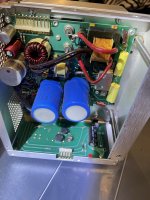
Here is my photo of the 5V output board with the large blue capacitor on the left measured shorted.
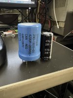
Here is the size difference between the Sprague capacitor and the Nichicon capacitor. And the next photo is after replacing the shorted capacitor with the Nichicon capacitor.
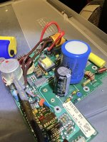
The Sprague capacitor has the outer four pins formed from the lip of the metal can - all those pins are ground. The + pin is between two of the ground pins and slightly towards the center of the capacitor. There is another + pin visible in my photo above near the edge of the Nichicon capacitor and connected to the 150K resistor next to the TESTED BY label. This resistor discharges C241 when the AC power switch is turned off. The resistor next to it discharges C441 when the AC power switch is turned off.
The Nichicon capacitor leads are 10mm apart - and easily fit in one of the two + pins and the adjacent ground pin.
The next photo is my completed repair with both Nichicon capacitors installed.
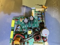
Be careful unsoldering these big capacitors - I messed up the large ground hole on C441 and had to install a wire jumper on the back side of the board.
This board did not connect all the capacitor ground pins - so make sure you select a ground that is connected before you solder the replacement capacitor.
After successfully powering on my 4054A - I rechecked the voltage on one of the TTL chips and got 5.05V!
I then ran a couple of my programs to test that I had not damaged anything else - including the Option 30 Refresh Coprocessor board, either of the two ROM Packs that were installed or my Flash Drive.
So I tested the ROM Packs by running my Bitmap program and displaying my Mandalorian with Grogu image.
Then I ran my latest Asteroid program work-in-progress - and the Option 30 board is also working fine!
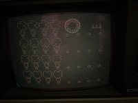
This photo shows running my Asteroid program which is displaying 99 Option 30 refresh objects:
Now I need to add four player missiles, 5 sets of score digits 0-9 and the two UFOs.
Then work on collision code and explosions.
Lots of fun!
I tried power cycling and all the front panel lights stayed on.
I removed the top cover and could see one of the four ALU board status LEDs stayed on, but the others never came on - which the 4052/4054 System Test Instruction manual indicates means ALU test failure.
I put my voltmeter on the power and ground pins of a TTL chip and only read 3.5V DC - so I have a 5V Power Supply problem.
My original 4054 computer also had a 5V power supply problem - and I posted in 2018 that it turned out to be a large 420uF 200V Sprague aluminum electrolytic capacitor C241 on the 5V output board that had shorted.
https://forum.vcfed.org/index.php?threads/tektronix-4054-troubleshooting.64433/post-781398
I removed the 5V Power Supply from my 4054A and took off the power supply cover and tested that same capacitor and it was also shorted.
This is a completely different power supply - so two failures of the same component sounds like a design problem - or the 'typical' vintage computer electrolytic capacitor problem.
In @BJeffway's thread https://forum.vcfed.org/index.php?threads/tektronix-4054-power-up-test-failure-and-diagnostics.1242027/ he reported today that he had previously replaced the same capacitor in his 4054!
I checked around for an exact replacement and didn't find any. This capacitor is over 40 years old - and likely a NOS capacitor might have an issue.
I decided to purchase two new Nichicon LGU-series 470uf 200V capacitor since there are two of these capacitors in the 5V output board. I bought two from Mouser electronics and installed them today and now my 4054A is working again!
However, if the Nichicon capacitor fails - it may be a design error. These two large capacitors filter the rectified main AC input. For my house the main AC voltage is 120V. The rectified outputs are listed on the schematic as +150V unregulated (filtered by C241) and -150V unregulated (filtered by C441). However, the rectified peak voltage from 120VAC input is 170V. The AC power in my neighborhood does go out occasionally, but more often it is off briefly (couple of seconds) and then is back on. Maybe the capacitors are seeing voltage surges above their rating.
My recommendation for this 4054/4054A 5V power supply problem in the future would be to select a higher voltage capacitor. Nichicon has 250V and higher capacitors at 420uF. The capacitors are slightly larger diameter than the 200V capacitors I bought, but I think they will still fit.
Here is my photo of the 5V output board with the large blue capacitor on the left measured shorted.

Here is the size difference between the Sprague capacitor and the Nichicon capacitor. And the next photo is after replacing the shorted capacitor with the Nichicon capacitor.


The Sprague capacitor has the outer four pins formed from the lip of the metal can - all those pins are ground. The + pin is between two of the ground pins and slightly towards the center of the capacitor. There is another + pin visible in my photo above near the edge of the Nichicon capacitor and connected to the 150K resistor next to the TESTED BY label. This resistor discharges C241 when the AC power switch is turned off. The resistor next to it discharges C441 when the AC power switch is turned off.
The Nichicon capacitor leads are 10mm apart - and easily fit in one of the two + pins and the adjacent ground pin.
The next photo is my completed repair with both Nichicon capacitors installed.

Be careful unsoldering these big capacitors - I messed up the large ground hole on C441 and had to install a wire jumper on the back side of the board.
This board did not connect all the capacitor ground pins - so make sure you select a ground that is connected before you solder the replacement capacitor.
After successfully powering on my 4054A - I rechecked the voltage on one of the TTL chips and got 5.05V!
I then ran a couple of my programs to test that I had not damaged anything else - including the Option 30 Refresh Coprocessor board, either of the two ROM Packs that were installed or my Flash Drive.
So I tested the ROM Packs by running my Bitmap program and displaying my Mandalorian with Grogu image.
Then I ran my latest Asteroid program work-in-progress - and the Option 30 board is also working fine!
This photo shows running my Asteroid program which is displaying 99 Option 30 refresh objects:
- Four different asteroid shapes in small / medium / large sizes and 4 copies of the medium and large and 8 copies of the small
- Sixteen player ships rotated at 22.5 degrees with sixteen thrust cones at the same angles
- 3 Extra player ships
Now I need to add four player missiles, 5 sets of score digits 0-9 and the two UFOs.
Then work on collision code and explosions.
Lots of fun!

Last edited:
