Muttley Black
Experienced Member
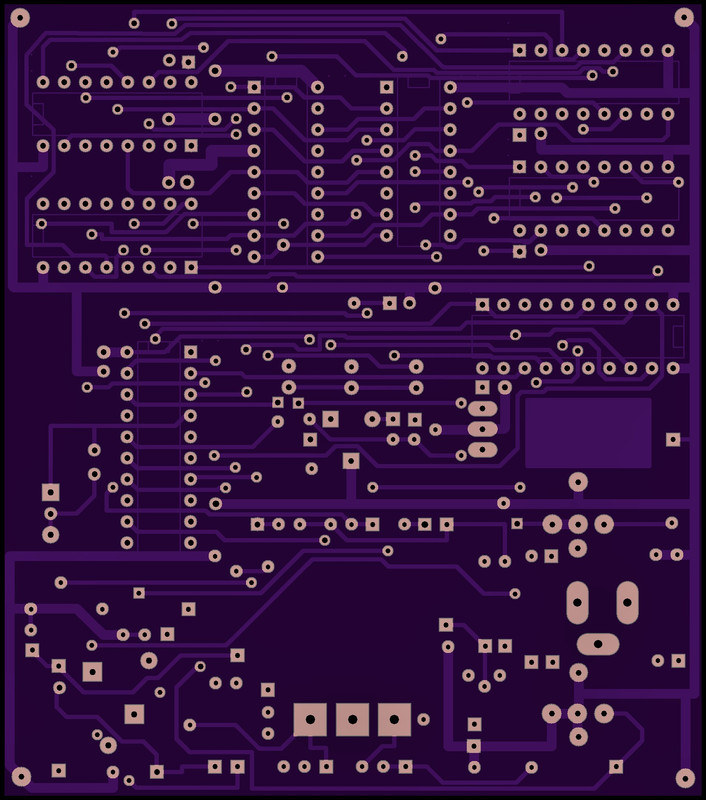
There are few days now that i am working on Startek dt-90 project. My goal was to keep the board same as the original and that was a bit tricky for me. I am not well known on electronics and pcb design but that was a good practice for me. On this one I try the mimicking by hand method, for the original old layout results.
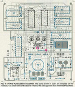
I would be very happy if somehow find a clear photo from both pcb sides, even with the components. That old and not so well pcb prints from the magazine makes my project a bit hard to finish. What i mean by that? If you look at the pcb mask, the one that have the components layout, LED4 (green/red) with the 3 legs sawing the negative leg soldered in the ground (top side), but in bottom side of the board soldered again in a ground track ( bottom side) but that time through R1 resistor (91ohm) for current limitation. How that led have current limitation in neg leg if already its soldered in clear ground on top side? Or the pcb prints have errors, or i didn't understand that part well. This problems is the cost if you want to make the pcb same with the original.
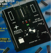
From my research, the only person i know who has one Startek DT-90, is one guy from the USA who repairs arcade machines. Is the same guy if i am not mistaken who buy's the last stock from the Startek company. Before some years sold the last one but kept one from himself.
I have send him emails for some photos or info's but never get an answer.
About Pal’s, the code is available too and this ic’s can be found. I don’t have Pal programmer but when this time come and all I need is that, I ask for help for someone that have one.
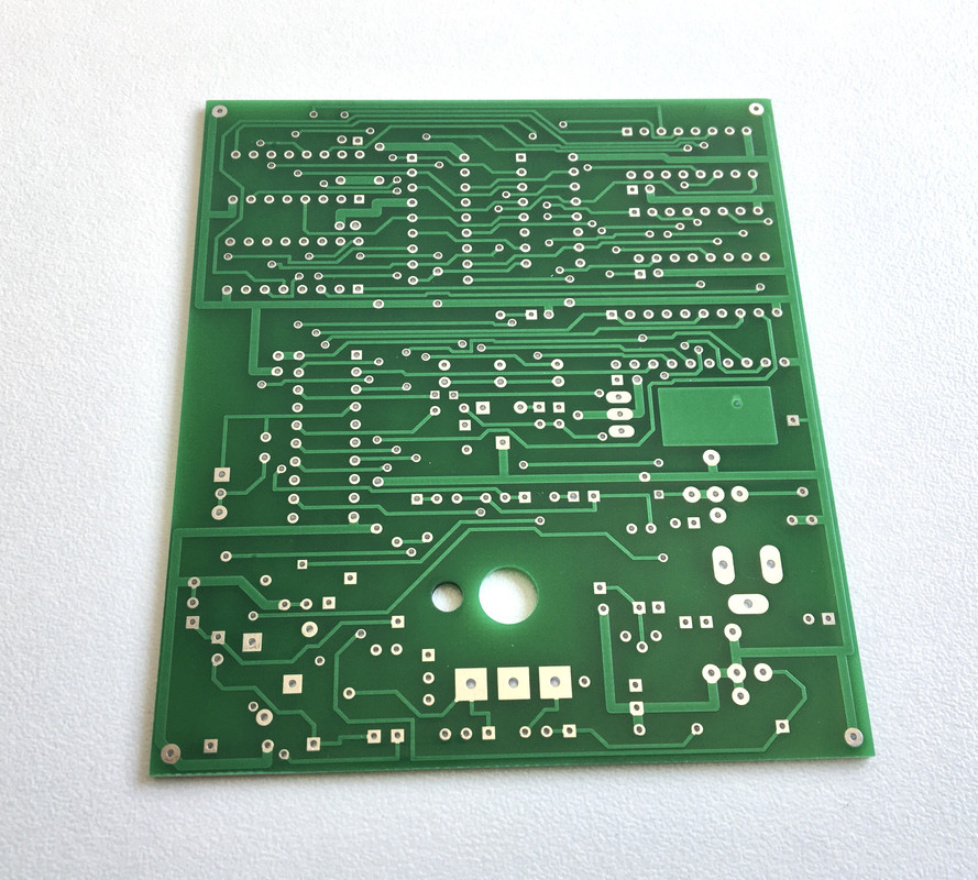
Board now finished but i need to do double checks before the printing process. It is not really matter if this try fail. We always have a second chance.
It was a pleasure for me to recreate that board.
We will see...
Top side view:
Last edited:
")