Upcoming Events:
- VCF South West - June 14 - 16, Davidson-Gundy Alumni Center at University of Texas at Dallas
- VCF West - Aug 2 - 3, Computer History Museum, Mountain View, CA
- VCF Midwest - Sept 7 - 8 2024, Schaumburg, IL
- VCF SoCal - Mid February 2025, Location TBD, Southern CA
- VCF East - April 2025, Infoage Museum, Wall NJ
-
Please review our updated Terms and Rules here
You are using an out of date browser. It may not display this or other websites correctly.
You should upgrade or use an alternative browser.
You should upgrade or use an alternative browser.
The Tale of the Good Kaypro and the Bad Kaypro
- Thread starter k6whp
- Start date
I have done so. The plugs on the FDDs are set correctly. A: is #1 (as in 0,1, 2, 3..etc. and B: is #2. The resistor plug is in drive B: per requirement.
So, if the A: (#1) won't function correctly when it is the only drive in the machine, what happens if you remove the A: (#1) and switch the #2 drive to #1 and try running that drive as A:, it being the only drive in the machine?
In other words what results do you get with only 1 FDD attached to the computer and do you get the same results no matter which FDD is the only FDD?
Look here; all common here is the universal board!
[...]
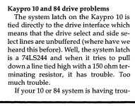
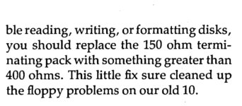
Micro Cornucopia, Number 19, August 1984, page 20
Interesting excerpts! William said he thinks his ROMs are 81-292 in the first post. Would that indicate a universal board? I thought they needed a later ROM revision.
rlauzon
Experienced Member
I had the same low voltage problem on my Kaypro "1" (Kaypro 1 case, Kaypro 2 ROM).
When I tried to replace the floppy drive with an HxC, it wouldn't work because of the low voltage.
Goteks, though, worked fine.
When I tried to replace the floppy drive with an HxC, it wouldn't work because of the low voltage.
Goteks, though, worked fine.
durgadas311
Veteran Member
The "universal ROM" is 81-478, the 81-292 was only "universal" in the sense that it targeted all the floppy models from 1984 (2/84, 4/84, 2X). The 81-478 would work on any later model - harddrive or floppy, high-/double-density. I don't believe there was much difference in the mainboards for all of those, aside from certain portions being depopulated, so the mainboards were somewhat "universal". But the term "universal" seemed to only come into wide usage with the 81-478 ROM ("UROM") and matching CP/M 2.2u1.Interesting excerpts! William said he thinks his ROMs are 81-292 in the first post. Would that indicate a universal board? I thought they needed a later ROM revision.
k6whp
Experienced Member
- Joined
- Mar 1, 2014
- Messages
- 71
Just reviewed my previous comments and have to laugh. "Oj"? and how does one "watch a sandwich"? (Would be nice if this forum offered an edit feature but..oh well..) Anyway, thanks to all who offered help!
Per the thread, I have swapped mostly everything from the good machine to the bad machine (and back) and the results are the same: the described failure. There are times when the bad machine "wakes up" but it always reverts to form. As for the four drives -- A: and B: on the good machine and A: and B: on the bad machine -- every permutation has been attempted with no success. That is the bad machine drives swapped to good machine and the good machine does not fail. Good machine drives swapped to bad machine and the bad machine fails. Same with B: for A: and A: for B: with no success. (Jumpering and resistor plug "settings" observed.)
Also, did you know that the A: power plugs have a different wiring than the B: plugs?
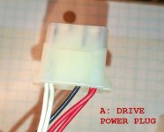
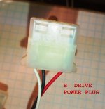
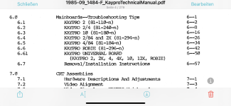
At the moment (well, tomorrow), I will be examining the DC wiring harness to check for intermittent/faulty connections and do a diagram. (See comments re Kaypro "tech manual" below.) I doubt I will find any problems.
But I am going to double back and focus on what the WDS1793 FDD controller tells me. Don't know what I'll find . because I am still digesting the datasheet. But we shall see what we shall see; it'll be an education.
Final comment on the "Tech manual" Kaypro produces. I have a lot of Tek[tronix] stuff on the bench (an old Tek 7704A scope and plugins) and have the service manuals to go with them. Clearly, the Kaypro tome is not up to those standards but it needn't have been. The manual was loosely put together from scribblings and notes from the Kays at NLS and meant to be hints about what's going on for the techs in the field. Not sour grapes on this; just realistic. But anyone engaged in endeavors like this should not expect the Encyclopedia Britannica or the like.
I don't; and that's why all y'all's help is greatly appreciated. Besides, the research is half the fun!
Probably offer up these two machines for parts or repair down the road. Think I'll get me a Raspberry Pi and do some Linux development work!

Thanks again!
Per the thread, I have swapped mostly everything from the good machine to the bad machine (and back) and the results are the same: the described failure. There are times when the bad machine "wakes up" but it always reverts to form. As for the four drives -- A: and B: on the good machine and A: and B: on the bad machine -- every permutation has been attempted with no success. That is the bad machine drives swapped to good machine and the good machine does not fail. Good machine drives swapped to bad machine and the bad machine fails. Same with B: for A: and A: for B: with no success. (Jumpering and resistor plug "settings" observed.)
Also, did you know that the A: power plugs have a different wiring than the B: plugs?


At the moment (well, tomorrow), I will be examining the DC wiring harness to check for intermittent/faulty connections and do a diagram. (See comments re Kaypro "tech manual" below.) I doubt I will find any problems.
But I am going to double back and focus on what the WDS1793 FDD controller tells me. Don't know what I'll find . because I am still digesting the datasheet. But we shall see what we shall see; it'll be an education.
Final comment on the "Tech manual" Kaypro produces. I have a lot of Tek[tronix] stuff on the bench (an old Tek 7704A scope and plugins) and have the service manuals to go with them. Clearly, the Kaypro tome is not up to those standards but it needn't have been. The manual was loosely put together from scribblings and notes from the Kays at NLS and meant to be hints about what's going on for the techs in the field. Not sour grapes on this; just realistic. But anyone engaged in endeavors like this should not expect the Encyclopedia Britannica or the like.
I don't; and that's why all y'all's help is greatly appreciated. Besides, the research is half the fun!
Probably offer up these two machines for parts or repair down the road. Think I'll get me a Raspberry Pi and do some Linux development work!
Thanks again!
haglebu
Experienced Member
durgadas311
Veteran Member
Note that the middle two pins on FDD power connectors are GROUND, and are connected together. So, those two connectors are effectively wired the same - Kaypro was simply saving the cost of a wire and the assembly was just not consistent about which GROUND pin was used. An EE might have words to say about current capacity, sending both 5V and 12V "return" through a single wire/pin, but the connections are not "wrong"....
Also, did you know that the A: power plugs have a different wiring than the B: plugs?
...
Thanks again!
durgadas311
Veteran Member
Although, the wiring anomaly does raise a question... are ALL the ground wires from the power supply working correctly? I see that the power wires (white and red) are daisy-chained, but the ground wires are separate. Your swapping of components might have already answered this, but could the ground wire to drive B: have a bad connection, causing "flaky" behavior?Note that the middle two pins on FDD power connectors are GROUND, and are connected together. So, those two connectors are effectively wired the same - Kaypro was simply saving the cost of a wire and the assembly was just not consistent about which GROUND pin was used. An EE might have words to say about current capacity, sending both 5V and 12V "return" through a single wire/pin, but the connections are not "wrong".
DeltaDon
Veteran Member
I believe the OP stated that moving both drives to the "good" machine and they both work with it. I find it interesting that the "bad" machine will load the OS, but not run a program. So the "A" drive does read the diskette well enough to boot the machine. Plus it is both drives that have the problem of running a program. So this problem is not limited to drive "B". Does this mean the problem is with executing some CPU instructions or with failures of some call routines in the OS or BIOS?
OBTW, the middle two pins on the power Molex connector are ground. Unless there's an issue with bad contacts it should not matter if the black wire in on one or the other of the the two pins.
OBTW, the middle two pins on the power Molex connector are ground. Unless there's an issue with bad contacts it should not matter if the black wire in on one or the other of the the two pins.
This has probably already been thought of and tested, but it hasn't been mentioned in the thread before. Are you booting up both machines with the same floopy? If not, one of the disks might be bad, i.e. the CP/M system might be corrupted on the Bad Machine's floppy, and fine on the Good Machine's floppy. Also, the CP/M might be the correct ROM-matching version on the Good Machine's floppy, but not on the Bad Machine's.
A final question which I'm not familiar enough with these machines to know the anser to: could the problem be solved by updating the ROM and CP/M to the 81-478 version?
A final question which I'm not familiar enough with these machines to know the anser to: could the problem be solved by updating the ROM and CP/M to the 81-478 version?
k6whp
Experienced Member
- Joined
- Mar 1, 2014
- Messages
- 71
..in the middle of producing a diagram of the harness on the 2X machines and will post it later today. So far, the circuits are pretty straightforward. Once you cut off the zip ties and spread it out, it makes sense.BTW, the middle two pins on the power Molex connector are ground. Unless there's an issue with bad contacts it should not matter if the black wire in on one or the other of the the two pins.
Alas, I have no schematic for the off-brand power supply and the marking on it are a little strange but not problematic. I'll take out the old faithful "suicide cord" and measure the naked voltages.
k6whp
Experienced Member
- Joined
- Mar 1, 2014
- Messages
- 71
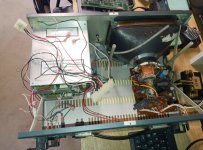
Per my promise, here's a rudimentary diagram of the 2X wiring harness -- simplified so as to be made understandable[?]. I did not find any problems with the harness (of course!) so I am shelving this and looking into the FDD controller chip (U44; the WD1793) as Doug recommended early on.
One way or another, I will report back here and share any results (good or bad) but the thread is outgrowing its usefulness owing to my kneejerk speculation and surmise. (The responses have been most helpful though.)
If the 2X ends up a smoking pile, so be it! It might be offered up for parts but I really itch to discover this problem. Consider it challenge!


