• Please review our updated Terms and Rules here

They may have found (most of) the Apple 1 Prototype Board

Still sticking to its been messed with. I think it was an early production unit, hence why the power section was torn off, to hide that fact. But hey some peeps have more money then brains.
 
I think you're correct on both counts. I've seen opinions that this must be the prototype because of the bodge wires. I didn't have the heart to point out that many production boards used bodge wires to make last-minute or field changes.
 
Wow. That's a lot of cash for that. I honestly don't know who to believe on authenticity. I'd be inclined to believe Woz et. al, but I know from first hand experience that memory isn't that reliable, and especially not over decades. My Dad and I were having a chat the other day about different cars he owned - I remembered his old 79 Grand Prix. I said yeah, big yellow thing. Dad says no, it was pink. I'm 100% sure it was yellow, he's positive it was pink. Someone has to be wrong. Either one of us or both. It's quite possible the actual Apple guys are misremembering. It could be that everyone is wrong. I'd be tempted to dismiss Corey on this one except for those darned resistor bands being aligned similarly. I can't see how that happens twice by random chance. Either that's the board in the Polaroids or someone's running some kind of con and moved them to match.
 
except for those darned resistor bands being aligned similarly

Ever bought a bunch of resistors in those rolls where the leads are held together by paper tape? All the resistors in the roll tend to have the same alignment. If you’re the schmo sitting there snatching and stuffing parts on a batch of boards with max efficiency I would wager there’s a decent chance multiple units will end up with them in the same orientation. (And you, the schmo, will go home and complain about how much your wrists hurt from the repetitive motion at the end of the day.) Personally I don’t think it’s as compelling a piece of evidence as advertised.
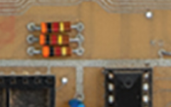
 
Ever bought a bunch of resistors in those rolls where the leads are held together by paper tape? All the resistors in the roll tend to have the same alignment. If you’re the schmo sitting there snatching and stuffing parts on a batch of boards with max efficiency I would wager there’s a decent chance multiple units will end up with them in the same orientation. (And you, the schmo, will go home and complain about how much your wrists hurt from the repetitive motion at the end of the day.) Personally I don’t think it’s as compelling a piece of evidence as advertised.
You might even do it intentionally because it makes it easier to visually compare and make sure you stuffed the sockets correctly if every board has the colours in the same order.
 
The thing with the resistors is not about simple orientation. Of course the resistors are all oriented consistently. Even a beginner hobbyist with a bit of pride in his build takes care of consistently orienting resistors, so the board looks neat.

As I understood it, the question of alignment refers to the slight offset of the resistors. This happens when you manually bend the leads, without the help of a bending tool. As a result, the resistor body is not exactly centered - and the offset will vary for each resistor. The combination of these offsets makes each manually soldered board unique.

If the resistor alignment exactly matches old photos, then this cannot be a coincidence. But of course it does not exclude a carefully made fake...

Photo showing the alignment of some resistors on the Apple-1 PCB in question. You can clearly see the alignment/offset, resulting from the manually bent leads:
1660982668987.png
 
The thing with the resistors is not about simple orientation.

Photo showing the alignment of some resistors on the Apple-1 PCB in question. You can clearly see the alignment/offset, resulting from the manually bent leads:

I agree, its either the same board or someone has 'tweaked' it to look the same, and maybe I like to think the best of people but I doubt its been tweaked.

The lack of 6502 capability means it must have been one of the very first whatever the argument about 'prototype'

Its all interesting, and thats what this hobby is about

but almost 700k !!!!!

Utterly daft, but hey. Somewhere someone has a grin from ear to ear.

Until they get it home. It’s junk.

I’ll take a apple IIgs over a apple 1 every single day.
 
Until they get it home. It’s junk.

I’ll take a apple IIgs over a apple 1 every single day.
Your talking usefulness of course.. But Im pretty sure ANY of us would gladly take an Apple-1 into our collection. ITs THE MOST OVERATED vintage computer out there, but it still has a place in collecting. The Apple-1 didnt make Apple the company it is. The Apple II Made Apple famous and wealthy.. It seems these fanboys and Jobs cultists keep trying to re-write history.
 
The thing with the resistors is not about simple orientation. Of course the resistors are all oriented consistently. Even a beginner hobbyist with a bit of pride in his build takes care of consistently orienting resistors, so the board looks neat.

As I understood it, the question of alignment refers to the slight offset of the resistors. This happens when you manually bend the leads, without the help of a bending tool. As a result, the resistor body is not exactly centered - and the offset will vary for each resistor. The combination of these offsets makes each manually soldered board unique.

If the resistor alignment exactly matches old photos, then this cannot be a coincidence. But of course it does not exclude a carefully made fake...

Photo showing the alignment of some resistors on the Apple-1 PCB in question. You can clearly see the alignment/offset, resulting from the manually bent leads:
View attachment 1245084

What is this original photo/polaroid we are all comparing this to? This thing?

450_1000.jpeg

I'm squinting to see any details here. IS there a higher resolution image I am not aware of?
 
Yeah.. those Polaroids are it, Next. there are some higher res photos on the Apple 1 registry site.. but as far as I know those are all that everyone is going on.
 
Your talking usefulness of course.. But Im pretty sure ANY of us would gladly take an Apple-1 into our collection. ITs THE MOST OVERATED vintage computer out there, but it still has a place in collecting. The Apple-1 didnt make Apple the company it is. The Apple II Made Apple famous and wealthy.. It seems these fanboys and Jobs cultists keep trying to re-write history.
Yes, it does have its place.

Without the A1 showing SW how not to build a 6502 machine, the A2 might not have been so good ?
 
The lack of 6502 capability means it must have been one of the very first whatever the argument about 'prototype'

Possible point of order here: according to the notes in the Apple 1 user manual those two points labeled “6502” are specifically supposed to be opened *only* if a 6800 CPU is installed. The manual doesn’t mention the 6501, probably because it was already basically discontinued by mid-1976 and any price difference between it and the 6502 had disappeared, but if you look at the schematics with regard to what changes on the motherboard when you open those jumpers it appears they concern tri-state address bus control and an “address valid” output... and despite being “pin-compatible” with the 6800 the 6501 critically lacks the tri-state control and just outputs a dummy VBE signal. Both pins are NC on a 6502 and a 6501 wouldn’t care either if they were disconnected. So… there’s actually a really good chance this version of the board supports a 6502, just omit the clock driver. What it *doesn’t* support… apparently, maybe there’s a trace cut alternative, is a 6800.
 
You can also see that one resistor has a wider orange band than the other two. Still not conclusive, but much harder to reproduce than mere staggering.

And that's a lot of money for an A1 that is unlikely it can ever be made operational because of all the missing chip positions. The best you could do is try to reproduce the missing parts of the circuit board, then Frankenstein it with dozens of bodge wires. Not that I even really care about A1, because memory-mapped video became a thing just as I started getting into electronics as a kid. I have no love for terminals that use shift register memory, just amazement that it worked at all.
 
Possible point of order here: according to the notes in the Apple 1 user manual those two points labeled “6502” are specifically supposed to be opened *only* if a 6800 CPU is installed. The manual doesn’t mention the 6501, probably because it was already basically discontinued by mid-1976 and any price difference between it and the 6502 had disappeared, but if you look at the schematics with regard to what changes on the motherboard when you open those jumpers it appears they concern tri-state address bus control and an “address valid” output... and despite being “pin-compatible” with the 6800 the 6501 critically lacks the tri-state control and just outputs a dummy VBE signal. Both pins are NC on a 6502 and a 6501 wouldn’t care either if they were disconnected. So… there’s actually a really good chance this version of the board supports a 6502, just omit the clock driver. What it *doesn’t* support… apparently, maybe there’s a trace cut alternative, is a 6800.

Chuck, I really understand that viewpoint, just that its interesting to delve :)

So looking deeper it did support a 6502 !

If you follow the traces on this board, pin 12 of B1 is connected to pin 24 of the PIA and pin 5 of the CPU as per the published circuit diagram.

For the 'normal' boards, there is a jumper to tie this line to +5v for the 6502 as the 6502 has pin 5 as N/C but a 6501 has pin 5 connected to Vcc.

This board I have noticed has a red jumper from the via on this line to the +5v rail so its obviously modified for the 6502, however the '6800' additional components were needed I believe in a 6501 populated board as only the 6502 had the internal clock driver. It also had the track to pin 3 of the CPU cut rather than remove Q1/Q2. Without the red jumper, the PIA would not have CS1 pulled high with a 6502, but it would with a 6501.

So a board that probably had a 6501 (or a 6800), but must have had a 6502 put in it and hand modified to make it work before the '6502 jumpers' were included on the PCB. From the photo, I think you can see the solder blob of the red link so it was demonstrated with the 6502.

The whole '6800' thing seems to be such an unused and breadboarding legacy thing, you wonder why its designation wasn't removed from the silkscreen when they put the 6502 jumpers in.

Then again, the drawings in the manual show the 6502 jumpers and the drawing done by a R Wayne in Feb 1976 which means precisely northing I suppose :) but then when was this board actually laid out ?
 
Last edited:
Back
Top