• Please review our updated Terms and Rules here

Time to start repair on my single sided 160KB Floppy drive..

You’re not using a hard sectored disk, right? I’m not sure what that would look like in IMD on a PC, but they do have more index holes, like 16 instead of 1.
 
Could the pot be bad and just moving it broke it?
You have a multimeter and so you can look for changing resistance (on the appropriate pins).

I once had a servo board that was running at the wrong speed and R4 would not adjust the speed. The problem turned out to be a capacitor (on the servo board) with a snapped leg, something that presumably happened during improper drive handling.

The circuit contains a feedback loop, and so the failure of a number of components can cause the symptom (running at wrong speed, and R4 does not change speed).
 
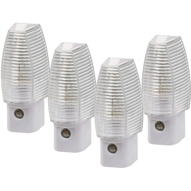
The traditional thing is a neon lamp (e.g. old night light). Some LED night lights also flicker because of imperfect filtering and they might do. Christmas tree LED lights are also like that--I can see the flicker and it's annoying as hell.
 
Is there a more comprehensive program?
I have my doubts about a certain adjustment pot not working. When I turn it the drive speed does not sound like its increasing or decreasing RPM

just curious, what is the ideal drive speed for one of these drives?
I watched a YouTube video where the guy couldn't adjust the drive speed with the adjustment pot & the fault turned out to be that LMxxxx IC.
 
The traditional thing is a neon lamp (e.g. old night light). Some LED night lights also flicker because of imperfect filtering and they might do. Christmas tree LED lights are also like that--I can see the flicker and it's annoying as hell.
regular office building fluorescent lights work for me
 
i have it i just dont have a light that can show me the pattern correctly. or maybe my eyes just cant see it.
I have put a video at [here]. In Australia, the mains frequency is 50 Hz, and so it is the middle ring that I need to look at. Notice how the black bars within the ring are stationary (i.e. not rotating). The light that I am using is from the overhead LED lights on the ceiling. I am sure that the black bars were more noticeable back in the days when I had fluorescent type ceiling lights.

You have an oscilloscope. See [here] for a circuit diagram of the servo board. The square wave signal on pin 2 of the LM2917N should be 300 Hz. You will be able to see that on your good TM100-2.
 
Nowadays, it's getting harder to find fluorescents--the compact ones don't flicker at 60 Hz (maybe some older ones do). And the 4' and 8' tubes are rapidly being replaced by LEDs, so it's not quite the same, but it's usable.

Me--years ago, I salvaged an old line cord and stuck an NE-2H in series with a 47K resistor inside a bit of clear vinyl hose. It's done decades of service.

You could do the same with a capacitive dropper and an LED and a diode. Or just pick up a cheap LED nightlight.
 
Chuck when you say nightlights I think of something completely different. For me a nightlight were those small incandecent lightbulbs. Same in size as the ones we used to use for outdoor christmas lights in the 80's, which had a plastic lens and a small photovolaic eye.
C7-Yellow-Opaque-Frosted-Incandescent-Bulb-Light-Christmas-IMG_7336.jpg
14f7b5ea-36f5-4121-8eb4-15d5dc188986_1.d8d2c567029bc10311a84a8d24abba6a.jpeg
 
The easiest thing to use that most vintage computer enthusiasts have at home and produce a 50 / 60 Hz strobe is a CRT. Darken your room and enjoy adjusting your drive in the blueish glow of a tube monitor / TV...
 
Those are old-style nightlights--they eat about 7 watts (IIRC). (I have converted a few of those to use inexpensive candelabra-based LEDs--you need to crack them open and solder a 100K resistor across the the lamp socket to get the photocell circuit to work. Most people would just toss them, but not yours truly. :) I can't see tossing something that can be made to work.
Modern nightlights (of the dollar-store variety) use LEDs.
 
So as I mentioned I borrowed a working motor board from my 5160's floppy drive to test this SS floppy drive. And I broken the green glue and turned the potentiometer. Well apparently that was enough to doom the pot as its no changing resistance value when turned. So.. piece of mind that thats what did in the working board. I ordered some new pots. I have replaced these same exact ones on apple II disk II floppy drives I just dont think I have any spares left.
 
Ok So The Single sided 160KB drive is now working again. I had to buy a set of LM2917 IC's from China: https://www.ebay.com/itm/283642744056 so that took a long while to come in. When they arrived I thought maybe they were counterfit as they didnt work in the speed board of this drive and another speedboard I was working on. Turns out there were a couple cracked traces at C5 and J1 (the #20 cable connector). The Speed pot at R4 was bad as well so I ordered a bag of them :https://www.ebay.com/itm/152164291793 Also from china, also took a while to arrive.

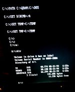
So, bad speed pot, bad LM2917 and 3 broken traces. The drive is now operating around 300RPM according to IMAGEDISK and I can format disks to 160KB and copy files to them.

As you can see I have files on it. Those are DOS 6.22 Boot files, of course it couldnt complete a boot but it started to and thats all I was looking for!
IMG_20221229_162106.jpg

Took a long time but I am closer to a working period correct early model 5150!
 
Back
Top