• Please review our updated Terms and Rules here

Toshiba T3200SXC Restoration - An effort 6 years in-progress...

T-Squared

Veteran Member
Joined
May 29, 2011
Messages
657
Location
San Antonio, TX
Urgh. This is one of the best computers I have ever seen, but the worst deteriorating system. Curse the capacitors!

Despite that, I have made efforts, and progress, thanks to an idea that Adalbert from Hackaday and Youtube brought forth.
I'm planning on putting a bit of a spin on his work, to make certain aspects less overbearing, and hopefully, at the same time, allowing old stock to have a purpose, and take up close-to the same room as the original components.

I see that I'm not the only one to have a problem with the rotting and leaking capacitors in both the screen and the computer's power supply. I went on a rant in 2017 about the original SHARP LQ10D013 screens being available, but not only being paywalled behind a ridiculous price most places online (At LEAST $1400?!), but also the fact that this stock is also rotting and degrading! (I tried buying another one for around $435 including S&H from China back then, but it was in the exact same condition as the Toshiba's original screen when I received it.) I did eventually find a "replacement" in the form of a Toshiba LTM10C013 (from one of the worst 386/486 systems I've ever come across, the T6400DXC), but that was extremely hard on the eyes, and something about its colors didn't agree with me (Yes, this an actual approximation):
EYut9gEXQAEXLDs.png

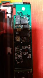
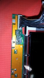
I've held onto another screen that I got around that time, which, this time, will seem to be clearer and less-harsh on the eyes (A Sharp LQ104V1DG21), along with 3D-printed supports both from Adalbert and myself (Don't worry, what you see as scratches, bubbles, and, at the corners of the screen, lifting of plastic, is just protection film that I haven't removed yet):
20230227_004939.jpg

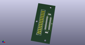
Right now I'm working on a Hirose DF9MA-31P-1V (LCD connector) to DF11-28DP (Toshiba video connector) adaptor, again based on Adalbert's design, so that way it can cleanly connect to the Toshiba without hacking-in the video connections. I might make the design available, if I complete it.

The power supply, though, is a different matter. I like the idea of the new design, but I'm not quite liking the idea of an external battery. I plan to add a charging circuit to the supply and get a LIPO battery to put inside the space once occupied by part of the power supply, as well as a visual charging meter on the proprietary peripheral slot, just so I don't have to guess how long a battery will last.

I do like the idea of the speakers, but I have also changed that as well. I have some 40mm speakers from an old cheap Chinesium (Thank you, CuriousMarc for adding a new word to my vocabulary) Bluetooth speaker that had its USB charging port ripped off, so I've 3D-printed supports for those as well.

20230227_014202.jpg

As for connecting the speakers to sound, I'm going to use a small slit on the side, normally used for holding the ISA card cover, as a way for the cables and 3.5mm connector to come out to the sound card.

As you can also see, I had to replace the original Citizen 26-pin floppy, but that was a while ago. I found a nice 26-pin-to-34-pin floppy adapter that still does need a 26-pin ribbon cable, but only needs two pins on the adapter to be tied to GND in order to work: https://www.ebay.com/itm/1655719231...uid=Gj9QMdF5TXq&widget_ver=artemis&media=COPY

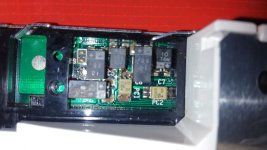
If you've been looking closely at this project, you may have noticed that the LCD is missing a backlight inverter board. For the moment, I have an LS520 inverter on its way, since it uses a connector standard that hasn't been used in almost 15 years. Chinese universal backlight inverter boards might work, but they don't use the correct connector.

Anyways, I've been chomping at the bit to get this done. I'm working on the computer's power supply, and the video adaptor board, but I need some help with finding a good charging circuit.
 
Last edited:
Here's the adapter for the screen so-far.
 

Attachments

  • Sharp LQ104V1DG21 Toshiba T3200SXC Adaptor.png
    Sharp LQ104V1DG21 Toshiba T3200SXC Adaptor.png
    136.4 KB · Views: 9
What made the original screen unrecoverable? I've had to deal with many LCD cap leaks but it's rare to have one that doesn't come back after. Damage to the internal display ribbons?
 
What made the original screen unrecoverable? I've had to deal with many LCD cap leaks but it's rare to have one that doesn't come back after. Damage to the internal display ribbons?
The electronics for the SXC's LQ10D013 screen are awkward in many places.

First off, there are areas on the screen which use the same kind of SMD electrolytics as the Sega Game Gear. (i.e. the capacitor lays flat, horizontally on the board, with the metal can surrounded in a rectangular package, and the leads come out at a right angle, down toward the SMD pads on the board.)
Unfortunately, this also means that they are very prone to leaking as well.

20180318_181342.jpg

They are also in awkward places on the screen.

20180318_182506.jpg

I tried cleaning the electrolyte off of different areas, but there is also a small module on the side, that sits on a set of metal riser-struts (not pins, nor SMD solder bridges) that also act as electrical conductors into the module's board. The module, I think has its traces completely exposed, as well.

This isn't the module, but is an example from a different project of mine, so you can understand what I mean (Although if you go back to the first image above, you can see the module near the bottom border of the picture, which has a MOSFET and an NEC 2501 chip on it):
20180317_215630.jpg

Anyways, the point is that these capacitors were very leaky, and the fact that the LQ10D013 is paywalled from $1400-to-at-least-$3000 means that there is a very niche market for them; no one will really buy them, except maybe hardcore retro enthusiasts, meaning that the capacitors on these screens rot and decay, taking the electronics with them, making them worthless. The new version I want to use doesn't have any electrolytics.
 

Attachments

  • 20180318_181325.jpg
    20180318_181325.jpg
    336.5 KB · Views: 4
  • 20180318_182458.jpg
    20180318_182458.jpg
    350.3 KB · Views: 6
  • 20180316_144535.jpg
    20180316_144535.jpg
    308.1 KB · Views: 10
I’ve run into those exact capacitors on the screens for my PowerBook 100 and my IBM PS/Note 425. Replaced them with tantalum caps, all working great now. Unless you’ve got internal damage to the ribbons going from the board to the glass panel itself, other parts can be repaired. Nothing in the images you showed looks too bad to me either.
Have you already replaced the offending caps and verified that it still won’t work with new ones? To each his own, but if I owned the first TFT color laptop, I’d want it to have its original TFT color screen in it for originality’s sake. I’d also not pay 1 grand for a replacement though for sure. It’s definitely useful to have replacement options but I’m curious about the original.
 
Oh, I know. I tried. I did use new capacitors. In fact, I even tried to use the little rectangular MLCC capacitors. Nothing worked.

I wanted to use the original screen and its electronics, but I'm finding out in recent years that sometimes there has to be a compromise.
 
Got it, just wondering one last thing: Did you ONLY try MLCC caps? They aren't well suited for operating in the conditions that a display expects. Mainly, their capacitance can vary depending on applied voltage. So in instances where the voltage sent through the caps varies (like on an LCD) you can have... issues.
In particular, drifty contast, but I wouldn't be surprised if it could cause considerable issues on a screen that early that's as complex as that one is. I've seen photos of the whole back of it and... wow.
Before I knew this fact about MLCC caps, I used them on a Sharp LM64P837 (64-gray Passive-matrix, from a PS/Note 425), a Sharp LM64P58 (1-bit B&W passive matrix, from a PowerBook 145) and a Sharp LQ9D01A (TFT Color Active-Matrix, from a PowerBook 180c).
The two passive displays have no real issues, but the Color one has major contrast issues. I haven't yet swapped the MLCCs for tantalum caps, but I suspect it's the issue. It will display white elements as dark gray until it "warms up" which is definitely not normal, along with other minor issues.
What were the exact symptoms of your display post-recap? And great perseverance over the years... I would not have gone as far as designing converters to retro-fit a new screen in there. Great job all around. Retrocomputing gets more high-maintenance every year. The Toshibas seem particularly bad about caps.
 
I don't believe I got a working screen at all. Nothing but white. It's been a long while, though. I think I did try to test the screen after each group of replaced capacitors. Even trying to remove the module-in-question was a pain, because the solder was ever-so-wicked into the strut vias (you know that feeling when you use solder wick, and yet it's still not enough to clear a via?), and I accidentally damaged the polarizer film with my heat gun.
 
Ah well… yeah heat guns and screens don’t mix. You mentioned buying a $400 replacement somewhere I believe? Same symptoms there? Solid white implies a signaling issue, something critical has failed. Could be caused by the cable or the screen. I’d just reinspect the traces, vias, anything although I assume you’ve done so many times. With polarizer damage though it’s a bit of a waste I suppose, although you can replace the film.
 
I have most of the components on the way, but I'm not going to really start until I have one last component, a large LIPO battery pack (hopefully with a protection circuit of its own) to fit within the space not taken up by the optimized power supply board, within the original PSU casing.
 
That was easier than I thought. (Yet somehow difficult, even with my soldering experience.) The pin adapter is finished!

20230314_120130.jpg


I'm working on a new power supply next.

I'm hoping to add in a battery-charging circuit. I need some help with a schematic, if possible.
 
Just wanted to add that the T6400sxc and dxc. Use the same TFT panel and can also be converted this way. I did something similar on mine with a similar sharp replacement panel.
Very happy to see you're making it more professional with a PCB. Because I spend way to long on mine hand soldering an adapter.
Are you planning on publishing the pcb files?
 
I was thinking about that.

I need to figure out what models I used to print the support brackets for the screen, because I had to test the fit quite a few times, and they're spread-out over multiple files.
 
Here is the archive for the connector converter board. I hope it contains everything.

Please note that this is NOT for the LQ104V1DW01 that adalbert used. This is for an LQ104V1DG21. The DW01 is physically smaller and seems to be more modern, despite the same display area. The DG21 is larger, and from 2002.

To use this, you need a Hirose DF9MA-31S-1V (LCD connector. It's "S", not "P", unlike what the first post of this topic will have you believe.), and a DF11-28DP (Toshiba video connector), with the missing pin 28 on the video cable harness pointing towards the top left of the board, on the side that reads "SXC PLUG ON THIS SIDE OF BOARD!"
 

Attachments

  • Toshiba T3200SXC to Sharp LCD.zip
    19.1 KB · Views: 8
Great, thanks. My T6400 is going to stay as is. It has been running great for a couple of years since I hand soldered an adapter. But this will probably come in handy when I finally get my T3200SXC back up and running, still waiting for a doner machine or someone to get me a one of the proprietary gate arrays to repair it's motherboard.

I've seen this same issue come up with a couple of early sharp TFT's, just a white screen after a full recap, even when there's no real damage.
Some that come to mind: Toshiba T3200SXC, T6400, Dolch first gen TFT. Ollivetti D33c, they all use very similar sharp TFT screens with the exact same issues.

And then you have the later models that all seem to work great after a full recap, like the later T6400's with the toshiba panel. and the sharp panel in the T6600
 
All right! I have good news! I may have a solution to make this thing truly portable! I have a NiMH battery pack coming in (It'll take a while to get here, but that gives me time to get the power supply design finished and sent off to OSHPark.)

From a Zenith Supersport SX, I have an external battery that I took apart in an attempt to repack it with new cells. I'm glad that I didn't sell it off with the computer back in 2020, because I think I can use the design of the electronics, with the NiMH batteries I have coming in. I'll make this charger design available as well, as soon as I have reverse-engineered it.
 
Last edited:
All right, I have my battery delivered! Now, I have a slight problem. I'm not sure my battery charging circuit diagram is complete. Can someone check my schematic to make sure that it is electrically sound? (Remember, I took this from a Zenith Supersport SX to reverse engineer it.)

I checked over this many times and tried my best to keep all the components straight. The battery and its positioning inside the original power supply case is a bit awkward, so I have to have two boards flanking it; one for the power input from the wall plug, the other for a board that converts for the power rails.
 

Attachments

  • Toshiba T3200SXC AC Input + Batt.pdf
    47.3 KB · Views: 5
I'm at a slight impasse until I can get the battery-charging circuitry rechecked. Don't worry about checking the schematic.

I'm making a simple photoshop schematic, of all 3 boards used in the Supersport for charging the battery, myself, to make it easier to follow the connections and double-check them. (One of them is already checked, leaving the comparator input board, and the actual power routing board.) Then I'll send off for the boards and parts.
 
Here is the archive for the connector converter board. I hope it contains everything.

Please note that this is NOT for the LQ104V1DW01 that adalbert used. This is for an LQ104V1DG21. The DW01 is physically smaller and seems to be more modern, despite the same display area. The DG21 is larger, and from 2002.

To use this, you need a Hirose DF9MA-31S-1V (LCD connector. It's "S", not "P", unlike what the first post of this topic will have you believe.), and a DF11-28DP (Toshiba video connector), with the missing pin 28 on the video cable harness pointing towards the top left of the board, on the side that reads "SXC PLUG ON THIS SIDE OF BOARD!"
Thanks for all of your efforts into working out a modern screen replacement. I have two original LCD panels and both of them exhibit the white screen issue.

Is the original inverter board compatible with the LQ104V1DG21?
 
I'm not sure about that. I would use an inverter board that was made for it. The cheapest one I could find and buy was an LS520 inverter board.

I haven't tested it because I'm still working on the power supply, but I've found that it's easier than finding the connectors for the DG21's CCFLs. (I'm assuming those have become obsolete.)
 
Back
Top