• Please review our updated Terms and Rules here

VECTREX WITH PROBLEMS

Not to panic!

On your version they may have removed these capacitors.

What we want then is the voltage:

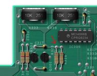
From the junction of the wiper of potentiometer R335 and resistor R334 to 0V and

From the junction of the wiper of potentiometer R333 and resistor R332 to 0V.

Follow the PCB tracking from the centre pins of the two potentiometers R335 and R333. They should be wired directly to two 3.3 MOhm resistors R334 and R332 respectively. It is the voltage reading from the identified pin of R334 to 0V and R332 to 0V that I require.

The alternative way is to note the position of potentiometer R335 and twiddle it slightly - first one way and then the other - to see what effect it has on the displayed image. It should shift the image to the left and right. However, at the end of the experiment, put the potentiometer back where it was please.

Dave
 
Can the DAC be bad - well unlikely because the Y direction is working correctly. It is only the X direction that is not working correctly. The DAC drives both the X and Y direction - therefore cannot be at fault...

We are trying to find a difference between the X and Y sides of the circuitry.

Dave
 
Right, but you still have potentiometers R335 and R333 on the edge of the board.

Follow the PCB tracks to the centre terminal of each potentiometer. Each potentiometer wiper should (I hope) go to a resistor.

I will see if I can find a service manual referring to your specific revision of the board.

Dave
Good morning, i can t see PCB tracks now because i must unscrew logic board from case console... And to do this i must desold some wires.. If necessary i ll do this , no problem!
 
Dave, can be this resistors maybe??
 

Attachments

  • Schermata 2022-01-23 alle 10.49.51.jpg
    Schermata 2022-01-23 alle 10.49.51.jpg
    129.9 KB · Views: 8
It is unlikely to be those resistors. They are commoned at one end and connected to one of the supply rails. Not so our resistors.

Is there a gap between the bottom of the PCB and the case? If so, you may be able to shine a light through the PCB and see the shadows of the tracks underneath.

I don’t seem to be able to find a schematic for your particular board unfortunately. Perhaps you can have a look to see what you can find?

Either that or ignore the reading for now and we will try something else. Something like the last paragraph of post #21.

Dave
 
Hi Dave, there isn't enough gap to see pcb....i desold the two reset wires and in try to unscrew the board
 
Read the last sentence of post #28 that points you to my text in the last paragraph of post #21.

We are going to adjust the X-shift control to see what happens and how much adjustment we have available to us.

Dave
 
Can you see enough of the centre pin of potentiometer R335 to attach a clip to it to measure the voltage from the wiper (centre pin) to 0V?

Have you had a look for the schematics for your specific revision of the cards?

Dave
 
Excellent - well not...

Note the current position of potentiometer R335.

This potentiometer should be connected on one side to +5V and the other side to -5V.

Can you check the voltage on one side pin of potentiometer R335 with respect to 0V and then the voltage on the other side pin of the same potentiometer with respect to 0V please.

Dave
 
Do you mean -4.94V or +4.94V relative to 0V?

Put your black (negative) multimeter lead on 0V and measure on the two outside pins of R335 again please.

In post #36 you identified the voltage as 4.94 (positive) and now as negative.

When taking voltage measurements with respect to 0V always put your multimeter negative (black) probe on 0V and then quote the sign of the voltage you are reading in addition to the magnitude.

Dave
 
I remeasured all tre R335 pins.... with black multimeter lead to ground i measured always -4,94 V!
 
Back
Top