• Please review our updated Terms and Rules here

Vertical ghosting lines on Iiyama CRT

Denniske1976

Experienced Member
Joined
Jan 17, 2011
Messages
480
Location
The Netherlands
Hi guys,

Dunno if this is the right section to post this, otherwise feel free to move the thread...

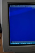
I've just picked up an Iiyama MF-8617T CRT and was quite happy that I've found one since I've used that BITD with my 486DX2-66 PC. Unfortunately when I switched it on I noticed three (kind of) vertical ghosting lines on the right side of the screen going all the way from top to bottom :-( Of course, no problem when I have my MS-DOS screen but in Windows, Word Perfect etc these are very annoyingly noticable.

DSC01576.jpg

So uhm, I was wondering: Is it very hard to get rid of these? I've tried a different VGA card and even switched from BNC to VGA cable but to no avail :-( Really too bad because this is one of my favorite screens from BITD.
 
I have a Dell monitor with the same problem.

It's the monitor itself that's the problem. It's almost certainly a problem with the analog circuitry or the power supply. It's probably fixable, but you'd need someone experienced with old CRT monitors to fix it.
 
Is it a Trinitron? Then it could be the raster wires clinging together. Just smacking the monitor on the side will 'reset' the raster wires.
 
Nope, it's not a Trinitron but the normal old MF-8617T (I had the pro as wel, with the Trinitron tube but those two wires were just too visible).

I have no experience with these kind of screens, so I'd probably have to bring it in to have it checked? Hmmm, dunno if it'd be better to look for another on then...
 
Vertical ringing / shadows on the left side of the screen is a weak capacitor in the voltage supply line feeding the crt RGB output transistors. It's usually like a +180VDC supply derived from the high voltage flyback transformer. It's called a scan derived supply. With a schematic I could show you which cap. It's usually somewhere around 47uf 200V. I used to service CRTs of all types in a repair shop for many years.

Larry G
 
Sorry, thinking on the fly here. Lower the brightness to reveal more of the distortion and take another picture and post it. That might reveal more of a vertical shadow pattern.
If it's the problem I'm describing you should see more of a dark bar on the left side. A yoke circuit impedance mismatch can cause many fine 'ringing' lines on the left side also. That would
involve tuning caps in the horizontal yoke circuit and very in-depth to find the problem. I'm hoping it's the former problem described. Anyone else with CRT shadow problems can try this also.
Dark vertical shadow on the left side is very likely the cap mentioned.

Larry G
 
Here's what I get with the contrast at 100% en brightness all low:

DSC01579.jpg
DSC01580.jpg

It doesn't seem to get worse from what I can see... so uhm, open the thing up and try finding that 47uF/200V thingie?
 
I can see a shadow line about an "inch" from the left so yes it's possibly that cap. Boy, it's going to be hard to ID by looking around. When you remove the back, look on the circuit board on the neck of the CRT - it could be there. The cap will be taller than the rest like maybe 3/4" to 1" tall and skinny. Also look around the flyback transformer which is the one with the anode wire going up to the CRT with the rubber cap. If you can take some pictures of the component side of those areas I'll see if I spot a possibility. Also pictures of the circuit side of those areas. Be careful about that anode lead at the CRT. Don't try to remove from CRT unless you know how to discharge it !! It will give you a good jolt !!

Larry G
 
If you open the monitor, be careful of high voltage. Try to avoid touching things.
The tube could potentially hold a charge of many kilovolts.
 
>If you run a ground wire to the HV terminal you will discharge it and there will be no further danger.

Yes, I didn't know if he'd have means to do this and might not be necessary just to take some pictures but the best is to have a wire with alligator clips, clip one end to the chassis frame and clip the other to a long skinny screwdriver and slide it under the rubber cap to touch the metal prongs. You'll hear a snap. Keep the screwdriver in place for maybe 10 seconds or so. Also, the charge will build up again slightly due to the
enormous capacitance of the CRT bell so always assume it has a charge and stay clear of the anode.
 
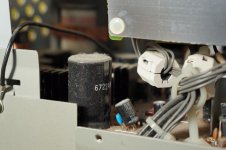
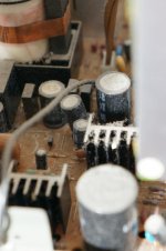
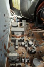
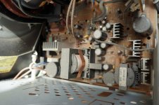
Well, I took some pictures of the left backside of the main board where all/most of the caps are... there's actually surprisingly little stuff in there. I was a bit hesitant to open it up since there was some kind of Xray warning sticker on the metal cage but I took off the top and back so I could get some pics done. It all looks OK to me, save for some dust everywhere:

00001.jpg
00002.jpg
00003.jpg
00004.jpg
00005.jpg
 
Yea, the pictures you took are all on the left side of the chassis where the main power supply is. The portion I need to see is on the right side of the CRT where the high voltage transformer is. Get as much of an aerial view looking down at the components
or looking up at the circuit foil side of the right of the CRT. Also the board on the end of the CRT. Problem is, those might be shielded from view with metal covers. The x-ray warning only applies to while the CRT is powered on and personally I think that's a myth. However, I serviced many CRT's while running disassembled and I am a lymphoma survivor so maybe there is truth to it :(

Larry G
 
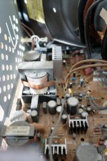
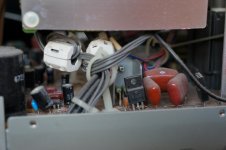
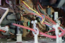
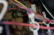
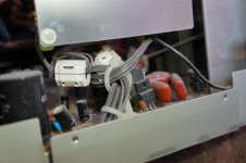
Are these any good for ya? Otherwise I need to take the right side of the cage apart, there's some cables attached to that piece of metal with nylon plugs so I need to be a bit more careful there...

00001.jpg
00002.jpg
00003.jpg
00004.jpg
00005.jpg
 
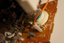
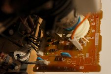
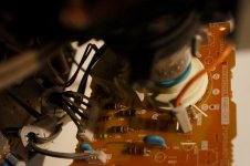
Good shots but I'm not seeing your R G B output transistors either. Picture #1 shows a white nylon button which holds the protector plastic on the circuit board on the neck of the CRT. You know how those release? Just gently pull on the cap with your fingernails will pull out the center pin and then the outside nylon hole will pull out with the plastic sheet. Then you could just rotate the sheet out of the way and take a picture of that circuit board and post. As long as the CRT hasn't been powered on for a few hours there will be no shock hazard there. Does it look like there's transistors or caps on that board?

Larry G
 
... The x-ray warning only applies to while the CRT is powered on and personally I think that's a myth. However, I serviced many CRT's while running disassembled and I am a lymphoma survivor so maybe there is truth to it :(

Well, it's certainly not a myth but not a big risk with CRTs made in the last ~two decades. In any CRT, all the components necessary to generate x-rays are present and work much more effectively with higher HV. The lower HV used now means the radiation is lower energy and stopped easily by lead or barium protection in the glass envelope. In this case, consider that as a consumer product the housing perimeter must be safe. The label simply tells you that the levels are higher inside the housing than what is allowed for continuous exposure. X-rays lose intensity by the radius squared so distance and time-limited exposure are the keys to your safety when working inside.

I designed industrial x-ray inspection systems for many years and in many cases a four-foot straight tunnel was sufficient standoff to get serious radiation levels (much higher than from a CRT) down to the very low level required by FDA law for industrial users, yet material to be inspected could flow in and out unimpeded.
 
Last edited:
Yea maybe myth was the wrong choice of word. I always felt there was too much emphasis on the "dangers" of a CRT. I remember being told as a kid to no sit too close to watch television because it could ruin my eyesight, etc.
I never serviced a television with the metal shroud off the CRT because there was no need to except to replace the tube and I did many of those. And of course I did replacements without using eye protection which was probably
stupid too. I remember seeing a training video where an imploded CRT actually drove glass into a concrete wall. But like was said, later CRT's were designed much safer and of course all the warning labels... but I was young and invincible :)

Mr. Denniske1976,

As far as repairing this display, if you want to post more pictures I'd be happy to study them but of course don't do too much disassembly because we don't want to turn a working display into one that doesn't :)
If it is the capacitor I'm thinking of, over time the lines will turn into a black bar down the left side of the screen and the rest of the display will keep getting brighter, eventually brighter until washed out.
The voltage supply is a cathode bias for the CRT which provides a black cutoff threshold. Boy, I love these big words ... :)
Seriously, the display will probably be fine for a few more years.

Larry G
 
I'll get some pics done when I get home... I'm based in Holland so there's a bit of a time difference between us (I'm at work right now and it's 14:30hr) ;-)
 
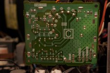
ok the next step will be to get pictures of the circuit traces of the board on the end of the CRT tube (by removing that protective sheet) and the component side. However, the board will probably be epoxy glued to the neck of the CRT along the glass so don't unplug from CRT if that's true because might damage the end of CRT. Just be gentle and do what you can and even take 'selfie' shots from the backside of the board.
Hopefully there isn't to much metal shielding in the way. Mainly need to see if there's output transistors on the board, any caps and on the circuit side include the connector that runs down to the main board. One of those wires has to be the supply we're looking for.

Larry G
 
Back
Top