• Please review our updated Terms and Rules here

Videos: Testing DEC H740 PSUs and PDP-8/f power on & simple tests

intabits

Experienced Member
Joined
Jan 22, 2019
Messages
148
Location
Melbourne, Australia
A couple of PDP related videos.

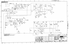
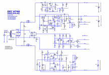
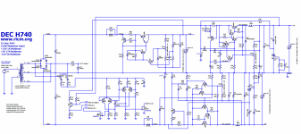
First video is testing the H740 power supplies from the PDP-8/f and PDP-11/05, with a dummy load.

I made the mistake of running the first PSU from a variac with the load attached, and damaged it.
The second PSU blew a fuse under load, not sure why.

After getting replacement parts, I fixed the 8/f PSU, tested it and installed it to the computer.
(repair of the 11/05 PSU can wait)

https://www.youtube.com/watch?v=n_fIjp-XNiM


Second video is powering up the PDP-8/f for the first time in over a decade.
At first I thought it wasn't working (yet another dumb mistake), but then realized it was OK after all.
I was able to enter and run a couple of small test programs.

https://www.youtube.com/watch?v=Be2dD2qwWAU
 
Great videos. Quite coincidentally I spent the last few days testing and repairing the H740 out of my newly acquired ME11-L. I managed to run mine up and down with a variac while under load (+5V @ 5A) without any drama. Maybe it was just time for your bridge rec to go?

Happily, the only thing wrong with my H740 was a bad AC / DC LO circuit due to a cracked zener (D3). Took me quite a bit of puzzling to figure out what was wrong, though.
 
If the H740 is a switching power supply, running the voltage up and down with a variac might not be the best idea. Early switchers were touchy about the AC power and running without a load.

At lower voltages the oscillator might not start and then you have what is basically a short circuit. I'm remembering back to my days in the '80s working with early switchers.
 
Great videos. Quite coincidentally I spent the last few days testing and repairing the H740 out of my newly acquired ME11-L. I managed to run mine up and down with a variac while under load (+5V @ 5A) without any drama. Maybe it was just time for your bridge rec to go?
Thanks.
I was able to run the variac up and down a few times also, before it blew.
Yours at 5A should have been safe, But I was running it considerably harder: drawing about 13 amps from the +5v, and about 5A from the -15v.

I don't know where the limits are, but some simplistic calculations:-
The total output power was 13*5 + 5*15 + 1*15 = 155W, which at the normal 28VAC transformer output means about 5.5A.
Halving the mains input drops the transformer voltage to 14V, so the current must increase to 11A, which should still be OK for a 35A bridge rectifier.
But that's ignoring losses, just for starters, and is also probably much too simplistic.

Maybe what BitWiz said explains it?

BitWiz: Note that the H740 is unlike modern switching PSUs, Its a sort of hybrid, using a transformer to take the mains down to 28VAC as input to the switcher,
which is a type of buck converter using an inductor and diode rather than a transformer operating at high frequency.

But then, I'm pretty sure that it's all operating at mains frequency, so there is no oscillator to fail?!
It will be interesting to see what failed in the other PSU...
 
The Omnibus chassis in the PDP-12 at the RICM uses the same H740 power supply. We had some interesting challenges fixing the power supply when it died. We did not understand how the primitive switcher worked, so we used LTspice to simulate it. That gave us an opportunity to measure current and voltage in places that would be very difficult in a real power supply. By comparing the simulated behavior to the real behavior we were able to track down the blown transistors. We also had some replacement transistors where the base and emitter were swapped from the originals. That slowed us down for a while too.
 
The point of a switching power supply is to run at a higher frequency than 60 Hz so that smaller transformers (coils) can be used. I am not familiar with the H740 so I"m not sure how they work. Most of the switchers I worked with in the 80's had switching frequencies in the 8 KHz to 20 KHz range.
 
I figured it was in that range. intabits there must be some kind of 10KHz oscillator circuit feeding the primary of the transformer at what ever the total rated power is. This circuit can be very sensitive in early switchers (usually the switching transistors, if my memory serves me).
 
The point of a switching power supply is to run at a higher frequency than 60 Hz so that smaller transformers (coils) can be used.

Which is right of course.
I was thinking of another supply, and misremembered the mains frequency as being part of it.

After the filter caps, there is no mains frequency (other than ripple), so of course that can't be it.
 
That is the problem when you get to our age, we have forgotten more than we remember :p. We just remember we knew it once when we were younger.
 
This is the H740 schematic. It appears to be self-oscillating (a relaxation oscillator?).


Click image for larger version  Name:	H740_RevH_Engineering_Drawings_Apr74-Page-000011s.png Views:	0 Size:	682.8 KB ID:	1225878

For interest, the H740 power elements are similar to the H777, which is well documented in chapter 3 of "BA11-L mounting box technical manual".
http://bitsavers.informatik.uni-stut...-001_Oct77.pdf

But the H777 uses a 555 runing at 20KHz to control the pass elements. (this is what I was thinking of this earlier)
 

Attachments

  • H740_RevH_Engineering_Drawings_Apr74-Page-000011s.png
    H740_RevH_Engineering_Drawings_Apr74-Page-000011s.png
    682.8 KB · Views: 3
  • H740_RevH_Engineering_Drawings_Apr74-Page-000011s.png
    H740_RevH_Engineering_Drawings_Apr74-Page-000011s.png
    682.8 KB · Views: 2
We did not understand how the primitive switcher worked, so we used LTspice to simulate it.
Thank you for making that available. Thankfully the regulator circuits in my H740 were working fine. I did, however, load your ltspice model in an attempt to puzzle out how the AC / DC LO circuit worked. Alas, that part of the supply wasn't part of the simulation (understandably so).
 
I did, however, load your ltspice model in an attempt to puzzle out how the AC / DC LO circuit worked. Alas, that part of the supply wasn't part of the simulation (understandably so).

If you add the AC / DC LO circuit I would be happy to add it to the LTspice version that I share.
 
Thanks for that.

H7450-Mod-1 I've added the missing circuitry, trying to abide by the existing layout, and with DEC's.

But VCFED won't let me upload RAR or ASC. Where can I put them?

DEC H740 in LTSpice - mod 1.png
H7450-Mod-1B My idea of how it should be drawn.


DEC H740 in LTSpice - mod 1B.png
Notes:
(Designators below are as used in H740_RevH_Engineering_Drawings_Apr74 Page 11 - except last group - Extras)

D3 should be 5.1V zener (LTSpice only had 1N750 = 4.1V)
Q14 & Q19 should be 2N5433 (LTSpice only had 2N5432 & 2N5434)

Some incorrect designators fixed:-
D6, D7, R35, R48, C5, Q5

Added missing components:-
C3

Added missing +5v Crowbar circuit:-
But Q11 & D11 just copied from -15v supply

Added J2 pin numbers

Enbiggened Trimpot designators

Extra components found in H740.asc?:-
C10, C13
 

Attachments

  • DEC H740 in LTSpice - mod 1B.png
    DEC H740 in LTSpice - mod 1B.png
    544.4 KB · Views: 3
  • DEC H740 in LTSpice - mod 1B.png
    DEC H740 in LTSpice - mod 1B.png
    544.4 KB · Views: 3
  • DEC H740 in LTSpice - mod 1.png
    DEC H740 in LTSpice - mod 1.png
    389.1 KB · Views: 3
Your schematic looks to be for a different version of the 5409728 regulator board than the ones in your video. In particular, the schematic shows the DC LO and AC LO outputs being driven by FETs, whereas your boards, which are similar to mine, use two germanium transistors:

Screenshot 2021-09-26 190019.jpeg

You can see these transistors at the far end of the board near the output caps ( 67 & 68 ):

Screenshot 2021-09-26 191032.jpeg
The docs lists these as 2N1308 and 2N1309. I couldn't find models for these either, and I'm not knowledgeable enough to create them from the datasheets.
 
The docs lists these as 2N1308 and 2N1309. I couldn't find models for these either, and I'm not knowledgeable enough to create them from the datasheets.

Maybe their germanium-ness isn't important, and you'd get away with modeling a similar silicon transistor there (2N2440, 2N2789, 2N3469)?

I used this thing to find similar transistors:
https://alltransistors.com/transistor.php?transistor=698

Vince
 
Your schematic looks to be for a different version of the 5409728 regulator board than the ones in your video. In particular, the schematic shows the DC LO and AC LO outputs being driven by FETs, whereas your boards, which are similar to mine, use two germanium transistors:

Thanks. My H740 problems (so far) have not gone past the rectifier bridge, so I never noticed that.

The diagram in post #5 is the only one I've found online for the H740, it's from the 8/M drawing set. (The schematic(s) in post #18 are the RICM LTSpice file with additions from the schematic in post #5)

I may have physical prints of other versions, but have not checked yet.

Where are the snippets that you posted from?
 
Back
Top