• Please review our updated Terms and Rules here

VT100 with RetroGraphics Enhancement

GanjaTron

Experienced Member
Joined
Jan 11, 2007
Messages
201
Hi folks,

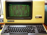
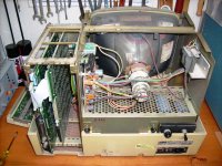
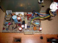
out of the blue I got my chance to own a real VT100 when I came across this baby literally sitting on a trash pile. It had a PSU problem (blown switching trannie and startup cap), but that was a cinch to fix with the tech manual on hand.

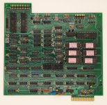
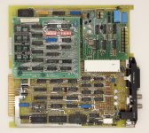
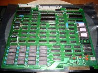
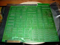
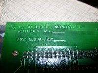
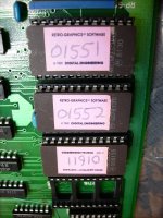
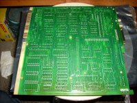
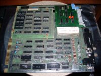
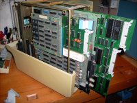
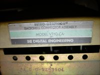
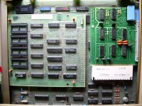
Apart from the basic logic board, this VT100 contains an additional VT640 board by Digital Engineering in the cardcage, apparently part of the RetroGraphics enhancement. I understand this is a Tek401x emulation, and managed to test it with gnuplot. That's as far as I got. Anybody know anything more about this upgrade, in particular where to get documentation?

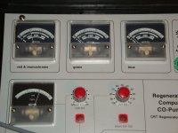
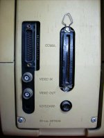
The rear connector panel includes a round 7-pin lightpen connector (see pic), although the lightpen appears to have been lost. Was this part of the RetroGraphics package or an optional extra? Any idea what type of pen was used? The connector doesn't look familiar.

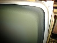
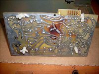
Lastly, the video output is distorted on the right side; it's slightly compressed vertically. I rearranged some of the magnets inside, but the result isn't satisfactory, and there are no keystone/pincushion adjustments on the (Elston) CRT board.

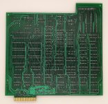
The problematic diode/cap combo on the CRT board was replaced in the early 90s (according to the cap's datecode) but checks out fine, so I didn't replace it. Having said that, the board is significantly charred in that location (see pic)!

Thanks for any help & info!

--GanjaTron
 

Attachments

  • DSCI3321a.JPG
    DSCI3321a.JPG
    53.6 KB · Views: 95
  • DSCI3162a.JPG
    DSCI3162a.JPG
    77 KB · Views: 87
  • DSCI3134a.JPG
    DSCI3134a.JPG
    40.2 KB · Views: 79
  • DSCI3232a.JPG
    DSCI3232a.JPG
    57.6 KB · Views: 68
  • DSCI3233a.JPG
    DSCI3233a.JPG
    58.1 KB · Views: 83
I had a TeleVideo 950 with some Retro-Graphics enhancements too.
I inquired about it here:
http://www.vintage-computer.com/vcf...hancement-quot-on-TVI-950&highlight=TeleVideo
(if that link doesn't work, do a search for "Retro-Graphics").


This was the reply I got from a TeleVideo guy who serviced the stuff way back when (to a question about what the Retro-Graphics stuff was all about):

As far as themodified 950 terminal is concerned. Televideo was one of the few MFG's who's PCBdesign was open to modifications. You might see terminals with modem piggybackboard modifications as well. Back in the day Mono Graphics displays were veryexpensive. Modifying a terminal was cost effective and had greater controlfunctions. Companies like GE, Reynolds & Reynolds and Status hadproprietary software programs that required a graphics interface. It's nosurprise you couldn't get the modified terminal to work. Without the properplatform to run it all you can use it for is parts. FYI, Televideo laterembraced the Mono Graphics niche and started modifying their terminals forthose customers. Starting with the 922/924 series then 955/9550 and finally9220G. In each case most of the terminals core components are the same and canbe either returned to stock mode or cannibalized for parts.

I may still have the boards if you need them - I ended up just removing them from my terminal.

The only other thing I found about Retro-Graphics (and it even mentions a VT-100) was at:
http://aea.web.psi.ch/Urs_Rohrer/MyWeb/trantext.htm
(when in the doc search for Retro and you'll find it quickly).

I've never seen any instructions about how to use it or what it did - IIRC, someone may have mentioned something such as it would store an extra page or two of typing.

This might be of help in trouble shooting the video problem:
http://www.repairfaq.org/REPAIR/F_monfaq1.html
 
Last edited:
The Elston video board is "charred" at that location because of the big power resistor right above the charred spot. This is not at all unusual for these boards, as I have seen this on almost every Elston VT100 board.

Otherwise, to straighten the image, you have to be very patient and iterative in your adjustment of the levers on the yoke. That's all there is to adjust. Honestly, your picture doesn't look that bad.

Keep your eyes out for other goodies on this trashpile, you have found quite a gem!

Lou
 
Well, 10+ years later and the VT100 still gets powered up every now and then. But it's starting to reek of BBQ after a while. I really should check those baked components on the Elston board. My home insurance doesn't cover "fire by VT100". ;^)

Oh btw, the Physics dept. has now closed off access to their trashpile. Probably too many weirdos running around sifting thru it. Security stuff, it's all hush-hush now, you know. Bloody paraNoidz. It was too good to last... :^(
 
Hi Al,
Good idea. Don't think there's many of these around. I now realise I didn't take any photos of the board itself. I expect it contains EPROMs, so my humble Data I/O should be able to read them. Where can I upload the ROMs and is there a preferred format?
 
I didn't know Data I/O ever made anything that was "humble".

I'd suggest either raw binary or Intel hex format, as both are universal. The latter is preferable due to built-in (minimal) checksumming of data.

I'd send them to Al Kossow for inclusion at Bitsavers.

Be sure to include a note (just a text file) indicating any revision information, if you have it, when it was read, with what, and what type of EPROMs they are.

-Dave
 
I didn't know Data I/O ever made anything that was "humble".
Hi Dave,

It's an entry-level (?) 288 which only handles EPROMs and some very early Flash devices. I've run into its limitations when I realised it doesn't handle GALs or serial EEPROMs. Still, it's a great extremely useful device since it's not tethered. It's been essential for most of my retrocomputing stuff, but as I said, it's limited compared to DATA I/O's higher end gear.
I'd suggest either raw binary or Intel hex format, as both are universal. The latter is preferable due to built-in (minimal) checksumming of data.
Ok, I've mostly used Motorola S-record but I there's a neat Linux utility to covert to whatever is preferred.

I just checked my archive and realised I _did_ take some photos of the boards. They're too big to email, so I'll just attach a few of them here in the hope they might be useful (and the forum doesn't object). Notice there's a daughterboard on the VT100 mainboard that interfaces with the RetroGraphics module via a ribbon cable. The firmware resides in three 2532's, so I should be able to read them.
 

Attachments

  • DSCI3185.JPG
    DSCI3185.JPG
    574.9 KB · Views: 43
  • DSCI3187.JPG
    DSCI3187.JPG
    568.2 KB · Views: 35
  • DSCI3191.JPG
    DSCI3191.JPG
    571.5 KB · Views: 33
  • DSCI3196.JPG
    DSCI3196.JPG
    534.7 KB · Views: 32
  • DSCI3179.JPG
    DSCI3179.JPG
    573.6 KB · Views: 36
  • DSCI3176.JPG
    DSCI3176.JPG
    566.6 KB · Views: 39
  • DSCI3170.JPG
    DSCI3170.JPG
    570.7 KB · Views: 39
  • DSCI3156.JPG
    DSCI3156.JPG
    536.7 KB · Views: 35
  • DSCI3155.JPG
    DSCI3155.JPG
    565.2 KB · Views: 31
  • DSCI3149.JPG
    DSCI3149.JPG
    561.5 KB · Views: 38
Ah yes, we discussed that on the Data I/O mailing list.
Mmmm, I remember those boards. I had a Retrographics setup back in the late 1980s. I really, really regret having sold it. There's essentially zero chance of finding one now. You got really lucky.

But yes, I think your Data I/O 288 will handle the MCM2532.

Actually I'd send all of those pics etc to Al for Bitsavers. The Retrographics system really deserves a directory of its own.

-Dave
 
Hi again Dave. I thought the Data I/O discussion sounded familiar. ;)

Let's just say I got lucky on this one occasion. The physics lab at the uni had some really interesting gear that got regularly tossed out. Went way beyond the usual PeeCee junk. It included video gear and lots of T&M stuff from the early 70s, but often missing parts. I also found parts of a CIT-101, but only kept the PCB (stupidly, I tossed the keyboard). The VT100 was an absolute fluke as it was intact and probably got dumped just hours before I went by. Obviously somebody had completely given up on it after the PSU blew, since it was a high hours unit anyway. Apparently it was used at one of the Max-Planck institutes. Anyway, those days are over, and security concerns have now made this pile off limits. :(

Having powered the VT up recently, I got concerned about the burnt smell. Both the PSU and the Elston video/deflection board are severely discoloured from hot components. Could this be a potential fire hazard? Like I said, this thing must have seen lots of use.

I'll try to find the time and crack this thing open again over the weekend. Does bitsavers have an upload directory where I can dump the ROMs and all the pics?

--Roland
 
you can email them to the adr at the bottom of the bitsavers.org home page
Hi Al,
thanks, will do. I'm actually standing in front of the VT now. Just pulled those cheapo plastic pegs. Got the Data I/O right here too. (And boy, is it loud!)

--Roland
 
Hi again Dave. I thought the Data I/O discussion sounded familiar. ;)

Yup. :)

Let's just say I got lucky on this one occasion. The physics lab at the uni had some really interesting gear that got regularly tossed out. Went way beyond the usual PeeCee junk. It included video gear and lots of T&M stuff from the early 70s, but often missing parts. I also found parts of a CIT-101, but only kept the PCB (stupidly, I tossed the keyboard). The VT100 was an absolute fluke as it was intact and probably got dumped just hours before I went by. Obviously somebody had completely given up on it after the PSU blew, since it was a high hours unit anyway. Apparently it was used at one of the Max-Planck institutes. Anyway, those days are over, and security concerns have now made this pile off limits. :(

Suits ruin everything eventually. But wow, what a find!

Having powered the VT up recently, I got concerned about the burnt smell. Both the PSU and the Elston video/deflection board are severely discoloured from hot components. Could this be a potential fire hazard? Like I said, this thing must have seen lots of use.

There's certainly a risk of things frying. I'd treat it with care and replace anything that needs it.

-Dave
 
Hi everyone,

I dumped the RetroGraphics ROMs last night, took some new pix of the main and interface boards. and just sent them to Al. Btw, the ROMs on the main VT100 board are the standard complement.

While I was at it, I checked the Clinton CRT with my Müter BMR "rejuvenator". This tube is basically on its last legs, but I didn't bother rejuving (and possibly toasting) it. Also, it's starting to delaminate around the edges (see piccie). This isn't noticeable (yet) when the bezel is mounted, but's only a matter of time. :(

--Roland
 

Attachments

  • DSC03600.JPG
    DSC03600.JPG
    1.4 MB · Views: 29
  • DSC03561.JPG
    DSC03561.JPG
    1.2 MB · Views: 28
I also have a VT100 with the RetroGraphics enhancement however my board looks very different to the one that Roland has posted. Roland's board appears to have a copyright date of 1981 whereas my board has a date of 1983.

Dump of the ROMs:

0561Y1_45E0 (U33)
0561Y2_E598 (U34)
0561Y3_0BE2 (U35)
0561Y4_9FDF (U41)
0561Y5_0A5C (U45)
0561Y6_3591 (U46)
XD2210 (U61) - NVRAM

Disassembly of the ROM:

Program ROM

Schematic of the boards:

Main Board
STP Interface

My board is not currently working, which is the reason why I started creating the schematic and disassembly.

Matt
 

Attachments

  • retrographics83_top.jpg
    retrographics83_top.jpg
    844.2 KB · Views: 26
  • retrographics83_bottom.jpg
    retrographics83_bottom.jpg
    1.1 MB · Views: 25
  • stp_interface83.jpg
    stp_interface83.jpg
    729.6 KB · Views: 26
Hello folks,

hmmm - eventually i should also have a look after my version.
Years ago i rescued also such a little beast.
The terminal without board runs fine, but connected nothing happens on the screen...

Best regards,
Kai
 
Whoa, look at all the RetroGraphics popping up everywhere. :biggrin:

There's at least two RetroGraphics boardsets for the VT100, namely the original VT640 I have, and Matt's Gen II. The interface boards are different too.

Note that the backshell was retrofitted as well, and features a lightpen connector, though the pen itself is gone on mine or it never had one in the first place. The case appears to have a mark where the pen holder may have once been attached.

Note also that there's a VT640 wikipedia page hosted on this forum: https://www.vcfed.org/forum/forum/genres/dec/76347-vt640-wikipedia-page
It links to a piccie of said lightpen in use, and a brochure.

Matt, did you scan those boards? Maybe I should try that too. My pix are crap.

--Roland
 
Last edited:
I used to have a scanner that would have worked quite well for these but my current scanner has a very short depth of field. Unless the object it pressed hard against the glass then it's out of focus.

For these pictures I used my (very) home made light box, which is basically a cardboard box with white paper stuck to the inside, some LED strip to provide illumination and a hole cut in the bottom for the camera. The board was placed on some white card, the box placed over then top (upside down) and then I took a picture through the hole.

I need to have another go at these pictures using one of my better cameras. I just used my phone camera in this instance and if you zoom right in then some of the detail is lost.
 

Attachments

  • box1.jpg
    box1.jpg
    118.2 KB · Views: 17
  • box2.jpg
    box2.jpg
    49.1 KB · Views: 18
Thanks for collecting these links! May I humbly suggest including a link to this forum thread: https://forum.vcfed.org/index.php?th...ancement.28533
You'll find some pix of my VT640 there. Al has the ROM dumps.

Regards,

--Roland

Hi Roland,

I had collected some links for a stub Wikipedia article for the VT640, but never created it as it seemed nobody had reliable sources of information about them at the time. It's great that there are now people who will be able to experiment and find out more about this mysterious machine!

While your suggestion to link to VCFed is a good one, I do not think forum threads are considered high quality citations on Wikipedia. We'd have to do a bit of extra work to make a proper Wikipedia entry.

My hope is that the folks who have VT640s will now be able to distill the research they do into a stable web page. (For example, it'd be great to have a comparison of the VT640 to DEC's official graphical terminal offerings, such as the VT55 DECScope.) Primary researchers aren't allowed to post their own work to Wikipedia. However, if they publish the information somewhere, such as a webpage, then the publication can that be cited by someone else, possibly me.

I am not sure if vcfed.org provides user editable pages for this purpose, but there are always options like neocities.org. By the way, if you do make a web page, please explicitly state that all images are copyrighted under CC0 (or other Wikipedia compatible license), otherwise they cannot be used on Wikipedia.
 
Note also that there's a VT640 wikipedia page hosted on this forum: https://www.vcfed.org/forum/forum/genres/dec/76347-vt640-wikipedia-page
It links to a piccie of said lightpen in use, and a brochure.

--Roland

It would be great to have an actual Wikipedia page which covered the VT640 (and clones), but it feels like there are a lot of unanswered questions. Since it was sold both as its own terminal (as with the Synclavier) and as an add-on board with specific graphics capabilities, the VT640 entry should answer the sort of questions one sees in both https://en.wikipedia.org/wiki/VT100 and
https://en.wikipedia.org/wiki/Waveform_graphics. What did it do (in brief, layman's terms), why was it significant, how is it related or compare to other systems (before, after, and contemporaneous), what were the pros and cons, what companies VT640-compatible cards, who used it and what for, when did it cease to be used and why?
 
Back
Top