• Please review our updated Terms and Rules here

WANTED: Software for Unimation Puma 560 robot.

Brake release.

Brake release.

I got the arm apart. Really interesting. I need to release the break of the base or the second joint. It seems locked, and it's really hard. I will try now to find the main cable and the teach pendant.
Anyone nows how to release the brakes?:confused:
 
Brakes

Brakes

The brakes are electromagnetic.
Energize them and they will release.

I will pull my tech manual tonight and look for the voltage, it that doesn't
work I will open mine and measure it for you.

When the brakes are off the arm will fall limp and could damage the gripper or wrist on the floor.
Be careful when releasing J2. Make sure you are holding it before you disengage the brake.

I'll post again soon.

-Mike
 
Brakes

Brakes

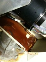
Thanks Mike! I took the arm apart today. There is like a brown red grease really solid and sticky. I guess that the arm was exposed to the sun and the heat melted the grease. Strange. I'm posting a picture.
 

Attachments

  • IMG_0158.jpg
    IMG_0158.jpg
    92.3 KB · Views: 2
  • IMG_0160.jpg
    IMG_0160.jpg
    92.2 KB · Views: 2
Yup, that’s bad grease all right.
You will need to clean all that out.
Then you will need to grease the joints.
You will need a grease gun (a cheap one will do)
And you may need to buy grease plugs, Zerts, or Grease points.
Everyone seems to call them something different.

I am not a grease expert but I am using a standard modern grease
Intended for farm equipment.

Also there seems to be at least 4 different grease plug sizes so make sure
Your gun matches the points you get/have.

I have scanned the Backlash and Cogging adjustment instructions and I am trying to upload it tonight. Look for a post later with a link.
 
ELECTRODUDE... I found more info!

ELECTRODUDE... I found more info!

ELECTRODUDE.
I found some other troubleshooting details.
I am uploading a maintenance manual tonight. Look for a link
Later. It should be www . Theatronics .com

All might not be lost.
 
Ariel: Brake Release voltage.

Ariel: Brake Release voltage.

The unlock voltage is about 16-17 volts DC.
In the base of the arm there is a Circuit board that connects to the position switch.

The system provides 22v to the pcb when the motors are running. There is a regulator on the board that knocks that down to 16.89vdc.

If the switch is left in NORMAL then all the motors will unlock.
Selecting one position will cause just that one brake to release when the
Button on the back is pressed.

When 22 V is provided and the switch is in any position other than NORMAL the button should light up.

The connector on the bottom corner of the board that has only3 wires on it goes to the button. The wires are Power, Lamp Return, Switch Return.

The smaller (24 pin) connector carries the 12 motor power signals (2 wires per motor)
They are paired (1,2) (3,4) (5,6) (7,8) (9,10) (11,12)
Pins 13-17 are not used.
Pins 18 and 19 provide the 22Vdc to the PCB. I am not sure what the polarity is.
It is important because of the voltage regulator and the diodes that are used to select all or a single brake.

-Mike
 
Cable.

Cable.

Mike, I tried to find that cable and it looks like is almost impossible to find. I'm considering your option of building one from scratch. Still once I build the cable I will need the software. Without the software and the teach pendant there is nothing I can do. If I had the robot complete, I will still need to find the software to make it run.
Is there a way we can find a copy somewhere?
 
need help

need help

Hello, I have a Unimation PUMA MARK ll Robot. It used to work, terminal, teach pendant, not the floppy though. I sold it to my nephew, He is into robotics at school. He got tierd of it and my brother gave it back to me.

They say it worked when they gave it back to me. When I fired it up it showed something on the terminal for a second or two then nothing.

I tried to hook up a pc with hyperterminal, not sure if I got it right.

controller turns on, fans run ? What should I do now. I'm not a electronics or robotics guy, but I feel confident to follow directions. The post about the batteries on the boards could be the problem?

Mark.
 
Is all lost?

Is all lost?

Ariel,
The cable is a straight through (at least mine is) Pin 1 goes to pin1 ect…
On my unit I have 2 cables.
The first (labeled J0A or just A) is smaller, it has 24 pins.
The first 12 pins are the motors. They appear to be 24Vdc brush motors so they are nothing special in the electronics sense.
As I mentioned in an earlier post they are paired 12,34,56,78,9-10,11,12
The next 5 pins are not used.
The last 7 pins are a bit more mysterious but with a little more work I could figure them out. They consist of the 24V supply to disengage the electric brakes on the joints,
Plus some other signal lines. Possibly a limit or safety sensor loop.

Each joint has a sine-encoder that has 4 wires connected to it. Additionally there are 3 sires that are connected to a variable resistor, or more accurately a potentiometer, and finally a ground wire. That makes 8 wires per joint.
Although I only have 6 joints on my unit, I noticed that the Circuit board in the base has an extra and unused connection for a 7th joint. So That makes 7 * 8 = 56 wires for the joint position sensors.

Allied Electronics carries the connectors that were used on the PUMA units so they are not hard to replace, the hard part is finding a cable. I would first look for some multi conductor wires and build the cable in bundles. LAN wiring uses 8 conductor wire so using a spool of CAT 4 wire you could run one length for each joint and then wire tie the whole bundle together when you are done. (For the Larger plug of course)

The smaller plug, for the first 12 wires, I would use a thicker wire because those wires provide the power to the motors. No less than 18ga. Don’t use speaker wire though.

Part of a wires current handling capability is it’s ability to disperse heat. Lamp cord and speaker wires have thick insulations on them that are meant to protect the wire from home owners who put chairs on them. They often overheat and cause fires because the think insulation keeps the heat trapped in the wire. Thinner insulation can be used for this application because the current the puma pulls is not high enough to overheat the wire.


On the issue of the software. I am working on that for you. I think that there may be a way to get you a copy of software. The issue I am checking into is how compatible the versions of the software are between the controllers.

The hardware changed quickly when the Pumas were being built so there seem to be a few different models. Plus the company changed hands a few times and each new owner put their own stamp on the product.

If you could send me all the serial numbers, model numbers and even any version numbers written on the EPROM chips in the controller I will try to find a match or donor for you.


The teach pendant might be a minor issue, I have seen them show up fairly cheap at times on ebay. But as a light of hope, The teach pendant is nothing more than a Serial terminal just like the VDT.

The only difference would be the E-Stop button on the top and the Dead-man switches on the back and on the side, and the speed/Slow switch . I am studying my pendant to see how I can write an emulator program to run on the PC.
The dead man switches and the E-Stop could be hardwired. And the Speed switch could be replaced with a simple toggle switch.

Once I get the communications down, the rest should be easy.

So in short, there is still hope.. Keep looking for parts and if you find spares, check with any other puma people you find. You might be able to swap parts for the ones you need.

-Mike
 
KRAMNHAZ , I'll try to help.

KRAMNHAZ , I'll try to help.

If the fans come on the may be hope.

The next thing to check is the Arm Power modules.
Power up the unit and turn the selector dial to position 4.
A button on the back of the arm should light up.
If it doesn’t don’t panic yet, the bulb could be burned out.
Press the button and you should hear a click.
The Wrist brake should have just unlocked.

You should be able to freely move the wrist joints now.

If that works then we can start looking at your computer.

You mentioned that SOMETHING came up on the terminal.
What does the teach pendant say?
I would expect it to say “Unimation” when you first power up.
Then it will go blank and after a moment you should hear a beep
And the teach pendant should say “NO VAL”

If you get that far then we need to look at your serial connections to the
PC.
On the back of my unit there are 3 smaller connectors and a larger one.
They are labeled AUX , Floppy, Teach, VDT/DISK

The larger one is the VDT DISK port. Some terminals had a floppy built in so they put both the terminal port and a duplicate of the floppy port in the one cable.

The vdt cable has 12 wires and they are labled A-B-C-D-E-F-G-H-J-K-L-M.
Notice there is no ‘I’.. I guess it looked too much like an L or J.

The pins are
A – floppy Rx
B – floppy Tx
C – Terminal Tx
D – Terminal Rx
E – Terminal Gnd
F – Baud Select (?? I didn’t use it so I am not sure)
G – J12 Disable ( Disables the other floppy port if this one is going to be used)
H – floppy GND
J – Negative 12vdc
K – Positive 12vdc
L – Positive 5vdc
M – Power supply Ground 0Vdc
 
Pictures

Pictures

Thank you Mike. I contacted a company that has all or many parts that we need. They told me that they even have the manual and documentation for sale. I will keep you posted on that info. Here I'm posting some pictures. One guy told me that my robot is not a 500. Its a 500 series but a 560. Now I need to know if it's a mkI or MKII.

Here is a link to the zip file with the pictures:

http://rapidshare.com/files/324557008/Archive.zip.html
 
THANKS! Great Pics!

THANKS! Great Pics!

Just got the pictures. Great collection!
I expect to spend some time going over each one pixel by pixel.

Your controller is very different than mine. I have seen that type before but never from the back. All 4 of the communications connectors on yours are the same size. I would guess that they are all the same pin-outs also (or nearly)

I am looking forward to getting more info on that company you found. I know of a few that sell Puma robots and parts, but they are very proud of the scraps they have. Because the manuals and documents a rare they seem to charge a lot. But I will check them out also.

Thanks again. MIKE
 
different controller

different controller

Thank you for your time and info, Mike

My controller has a manual control connection port on the front panel, lower LEFT side for the teach pendant.

On the back it has three connection ports, from left to right ACCESS, FLOPPY DISC, and TERMINAL , lower right side, and one more connection port called ARM PWR PORT.

Above the front panel are some switches, BRK/RLS, RUN/HALT, INT a momentary switch, LED's AMP A, AMP B, AMP C, 40 VOLTS, RUN. The RUN LED lights when I turn on the controller power switch.

The teach pendent readout flashes for a second when I power up the controller then nothing, the floppy LED flashes also, after the floppy LED flashes once the LED comes on again and I hear a click from the floppy drive.

I changed my Terminal cable to try to connect to a pc. My terminal is a ADDS Regent 20 according to the manuals that I have.

The manual says VOLUME l - EQUIPMENT MANUAL 398P1A, Unimation Robotics FEBUARY 1983 and VOLUME ll USER'S GUIDE TO VAL , Version 560.18.1A

My terminal shows letters briefly when I turn the power on and off again.

I don't seem to have a light on my arm or a connector like what you were discribing. My PUMA is like the one on E-BAY that Ariel sent you a link too.
The controller looks like the one in the pics from Alan Kilian.
My teach pendant is different than the one in the manual, it may be older?

Thank you for helping. Mark
 
Last edited:
ELECTRODUDE : Alignment Marks

ELECTRODUDE : Alignment Marks

Did you get any further with your trouble shooting? I have posted parts of the manuals I have gathered together on my website under
ROBOTICS
|_ PUMA
|_ Documents.

I'll send you the password to the documents site in a private mesg.

-Mike
 
Merry Xmas!!!

Merry Xmas!!!

Happy holidays to everyone here on the forum!!
 
No luck yet

No luck yet

Mike

No, I haven't gotten anywhere yet. I've just been surfing/researching as much as I can online and waiting on the guy who I bought it from to get back to me when he finds out how the one he has boots. Any info you can give me, I will very much appreciate it!!

Thanks again for all the help you have already given me and others.
Geoff
 
I have a set of documents posted that might be some help. There is a troubleshooting section that may be helpful.

I'll send you a personal message with the access info. I don't want to post it publicly.

-Mike
 
Thanks Mike. BTW the website looks good.

Looking at the troubleshooting manual, everything looks good except maybe the CPU, Memory, "A" Interface, or Communication board is bad. I was looking at Brynn's Puma 560 website (http://bobodyne.com/web-docs/robots/Puma560/Inside_1.jpg) and his controller looks like the one I have except the modules are not in the same slots. Any advice on if these may have been swapped? I can send a pic if it would help.

Thanks again,
Geoff
 
Also, the 4-Port Communication card has the connectors labeled J20-J23, back to front of controller, but connected to J10-J13 labeled connectors. They are connected as follows: J20-J11, J21-J13, J22-J12, and J23-J10. The connectors on the controller are labeled as followed: J10-Terminal, J11-Teach, J12-Floppy, and J13-Access. Any ideas on this?

Thanks,
Geoff
 
The only things I know about Board positioning is the first few boards.
The CPU should be in the first slot,
Then the memory boards (rom and ram),
And finally the Serial communications board.

They all need to be right next to each other because there is some sort of daisy-chain
Effect where signals are passed from one board to the next. The there is a gap the signals
Will not travel.

The I/O boards on most controllers seem to break this tradition. Apparently they do not use the interrupt system so they do not need to be in any particular slot, Although they do appear to be addressed so you will have to make sure they have different addresses set with dip-switches or jumpers.

On the serial card,
Each connection is made up of a PORT and JUMPER. Or at least that’s what I have always called them. Basically, “Tab T” goes into “Slot S” just as “Jumper J” goes into “Port P”

Each JP pair is uniquely numbered throughout the system, thus the numbers where the ribbon cables meet the card will not be the same as the connectors on the back of the controller.

Just think of the whole thing drawn out as a giant schematic, If I had two buss wires labeled J11, How would I how where each one goes in the drawing?

I am still researching and learning, but from what I can tell, the Terminal, Floppy, and AUX ports are fairly simple serial ports.

The TEACH port has the same serial port connections but it also has some safety wires.
A ‘Deadman’ loop and a E-Stop loop.
Both the E-stop loop and the ‘Deadman’ must be closed before the arm will move.

The Deadman is normally held closed by a button on the back of the pendant that is pushed in when the pendant is hanging on it’s post. Or by the thumb switch on the side that is held in by a mobile operator. (thus the name ‘Deadman’.. Should the arm strike the operator and knock them out, hopefully the pendant will be released and the switch will cause the robot to power down. I suppose ‘Knocked Stupid by a robot’ switch was not nearly as scary as “Deadman” switch.
 
Back
Top