• Please review our updated Terms and Rules here

XT 130W PSU 120V tp 240V conversion, is it possible?

mR_Slug

Veteran Member
Joined
Nov 28, 2006
Messages
941
Location
UK
I've been scouring modem7's site, and here for some info but still cant make heads or tales of it. Can you convert the XT PSU to run on 240V? Specifically the one with the P/N 1501436. I wondered if by '83 they built a dual voltage version, and its just a trace inside that needs to be cut?
 
Last edited:
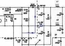
If it's the same circuit as what's in the docs, you can, and it's easy if you're willing to get out your soldering iron. Here's what I PMed to one of our members last week and he reported success.
The schematic is here: http://minuszerodegrees.net/5160/psu/5160_psu_schematic.htm
Do all this on the "AC INPUT BOARD."

1. Break the trace at PL/SK102 pin 4. The right side (output) of that path will now not be connected to anything.
2. From the left side of that path (output of R104) connect a diode to provide power to PL/SK102 pin 5. So the diode points toward pin 5. Use the same diode type as in the 5150 conversion (1N5404 or 1N5408 ).
3. From the left side of that path (as above) connect a diode to draw power from PL/SK102 pin 3. The diode points away from pin 3.

The circuits around Z4 and RL101 look to be unaffected. It would be wise (but not essential) to replace C101, C104 with modern "X2" caps, same sizes but higher rating than 250, say 280VAC roughly. Replace C105, C106 with modern "Y2" caps, same higher rating. Big caps C1, C2, C3, C4 on the main board can be replaced at your option ... or if they look dodgy.

It might pay to first do a test. Disconnect PL/SK102 (the connector) and confirm that the voltage at PL/SK102 between pin 5 and pin 3 is ballpark about 325 VDC running via a stepdown transformer. After you do the conversion, check for the same voltage running off raw 230VAC, and verify that pin 4 is not connected. That way you don't risk the whole PS.
 
Last edited:
It is common for these supplies to have a jumper to select
between 120 and 240.
Usually it is converting the rectification from a doubling circuit
to a single wave rectifier.
You can verify if this can be done by measuring the voltages
on the large input capacitors.
Always do this by safely connecting the leads to the capacitor
with it powered down. The DC level on these capacitors is
clearly lethal.
Always discharge them after removing the power. The usually have
a bleeder resistor but these are known to go open, leaving
a nasty charge on the capacitor.
Tinker Dwight
 
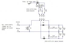
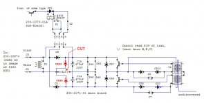
Is this what you mean:
PSU-mod.jpg

I will have to crack open the PSU tomorrow and see if it matches the diagram. Sure looks simpler than the 5150 mod. That resistor installation is a work of art!
Thanks
 
Is this what you mean:
That's correct ... and thanks :)

Note that there appears to be no fuse on the AC line, same as the 5170.
No idea why IBM left this out but be sure to check that the X2 and Y2 caps are suitably rated and in good shape.
 
Last edited:
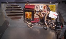
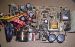
Well it seems I must have an early version of the XT PSU. The AC input board only has 2 wires coming out of it to the main board. In fact that part of the PSU is exactly the same P/N 204-1076c. The main board unfortunately isn't just a beefed up version of the 63W PSU:
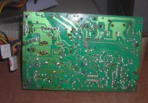
Dscn1561.jpg

Dscn1564.jpg

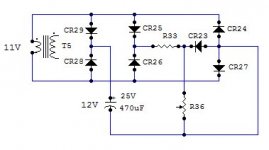
I have tried to decipher the main board and I think this is correct. (Resistor values are just placeholders):
diagram.jpg

It looks like it may be possible to do a similar mod, but T5 is an issue. I can't work out what ratio it is, its labeled "eia 343 95-3601". I have been unable to power the PSU up on 120V as I cant seem to find my step-down transformer anywhere, very puzzling.

Anyway, I was thinking that perhaps I could disconnect the secondary side and run 240V through the tranny, then somehow come up with something to reduce the voltage down to the required voltage. Wont the voltage be doubled, and the amperage be halved? AFAIK it is immediately rectified, and there is what looks like a smoothing cap rated at 25V. I don't know that much about transformers, so I may have got this wrong. The alternative is to find a new transformer with the right ratio.

Am I going down the right path here?
Does anyone else loose large heavy objects, like transformers?
 
Can we see the bottom of the board with the transformer.
I what to see if it might have a center tap primary.
As it is, you can't do much with it.
Dwight
 
... run 240V through the tranny, then somehow come up with something to reduce the voltage down to the required voltage. Wont the voltage be doubled, and the amperage be halved? ... I don't know that much about transformers, so I may have got this wrong.
Am I going down the right path here?
No, don't do what you propose, please ;), you will burn it up. You should be able to source a proper 240VAC-to-whatever transformer once you know what the output is.

First, update your schematic covering the secondary side of T5. Then, power it up off your stepdown (carefully, please) measure the DC voltage across the smoothing cap on that output, I'm guessing it's around 25V. You might want to temporarily solder some wires to the relevant pads for measuring so you don't risk shorting something with the voltmeter probes while it's "live." After you power it down be careful of residual voltages on C14, C15 ... could be up to 162 VDC on each.

Next, update your schematic with any further items connected to the junction between the caps you have marked C14 and C15. Hopefully there's nothing else so you can change to full wave without further issues.
 
Last edited:
If I'm making out the transformer correctly, there are only 4 leads.
So, no extra lead to be an input tap.
If you can't find your step down transformer, you can test the transformer
you have to see what its value is.
You have to unsolder it. Use one of your wall warts that has an AC output
and connect it to the primary. You can then measure the input and output
voltages. That will give you the ratio to apply to 120v.
Then you can hunt for a transformer that is close. Some of the wall warts
have transformers that are easy to rewind and aren't potted.
If you can find a small transformer that is for 240 and has a center tap primary, you can
use it as a auto transformer to drop the voltage. The core should weight about 1/2 the
T5 as it only deals with 1/2 the power in the core.
I did this once with a printer rated at 220-240 to bring it up from my 110-120v.
It is the other way but the principle is the same. I'd only use it on the T5 as the change of
the diodes is better for the raw input.
Dwight
 
Ok well here is the updated schematic:
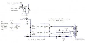
updated.jpg
secondary.jpg

The voltage on my secondary seems to be 12VDC across the cap. The 11VAC across the transformer, is likely the result of my multimeter (1-2V accuracy). The third leg of pot R36 goes off to one of the chips. I tried to continue with the circuit diagram further but it gets real confusing.

So I guess I need to find a transformer that ~20:1. I suppose a 12VDC wall-wart should suffice.

Here is what I'm proposing to do:

As I understand it, R33, CR23 and R36 are there to provide a voltage drop to the third terminal of R36. For the moment I will take out the transformer, and in its place on the secondary side, connect 12V DC, from a wall wart. It's rectified, again giving 1.4V loss. But I would rather not desolder/solder, more than I have to. Correct me if I'm wrong but 1.4V loss isn't going to screw up the PSU is it? Alternatively connect 12VDC across the Cap and 12V between CR23 and CR26.

Then power the device, on 120V, and the 12VDC wall-wart. It this works, Perform the mod to full wave rectification, test, on 240V, then crack open the wall wart and try to somehow fit it in the PSU.

One thing I need to do first is mod my step down transformer. It's a tool transformer. For those of you who don't know about these uniquely British devices, they are wired to provide two 60V hot leads. The ground point is actually between the 120V. Fine for tools, but if powering a 120V computer and then you connect that computer to something else, that's also grounded, as I understand it you end up with a 60V difference in ground points! Somehow this hasn't been a problem when connecting a 240V monitor to a 120V PC, and I cant understand why? So I'm going to mod it to provide, float, 60V-60V and GND-120V.

Dwight, just to clarify, do you mean to use the auto-transformer arrangement ONLY if I cant find a transformer of the correct ratio?

Thanks for your help so far.
 
Last edited:
OK well I've made some progress. The tool transformer has been modified and is working. I've removed the PSU's transformer (T5), and done the full-wave rectification mod. I can now power the PSU from 240V with 12V being supplied to the secondary side of where T5 used to be.

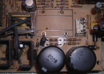
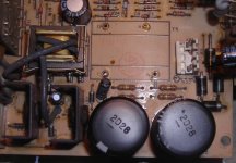
I don't know why I didn't see it before but there are actually places left on the PCB for the additional diodes. See to the right of the connector, CR35 and CR34. Also just below the connector, the bridge W23 needs to be removed:
Before:
before.jpg
After:
after.jpg
Updated Schematic (red indicates changes):
newdiagram.jpg

So this indicates that the board is designed with dual voltage in mind. So my question is now, can the existing transformer be used, and the secondary circuit be modified easily? Or was the intention of the designer to swap the transformer depending on whether the PSU was targeted for 240 or 120V?

If the existing transformer were used its now going to put out 24V, the smoothing cap is rated at 25V, but that seems a little close. This leads me to think the designer intended a transformer swap.

The transformer swap seems like the safest option. But I wondered if anyone more familiar with SMPS, would look at this (admittedly abstract) configuration, and recognize it? Or am I just chasing a ghost here?

Thanks
 
The transformer must be changed or another source of 12VDC maintained across the 470uF 25V cap. Yes, the designer intended a transformer swap. If you run that one off 240VAC it will fry in a few minutes! As Dwight said, you might find a suitable transformer inside an old (non-switch mode) wall wart.

Or look in Digikey. You will need to measure the DC current used by your wall wart to supply this circuit to size the transformer.
Mouser has a better selection. If you measure both the current and physical size it would be easier for us to help further.

Otherwise good work, and please maintain good electrical safety. Your work-site stepdown would have been better left with either a centre-grounded 120 VAC or even floating. But, you're past that point now.
 
Last edited:
Thanks. Saved me chasing that ghost. I will first try to crack open the wall-wort I have. The one I'm using is a very common generic shaped one here in the UK, and feels like its not potted. If it will fit then it is an easy source for replacement transformers, in case anyone else wants to perform the mod.

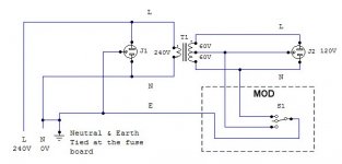
I've wired the tool transformer to have the ground point switchable. There is float, 60-60V, and 0-120V. Usually the center point is tied directly to Earth. In the image below, I have made this switchable to set it so that instead the neutral of the 120VAC is now 0V with respect to earth. This is what you have in the USA right?

tool.jpg

I hope this makes sense. As I understand it the floating type is the safest when working on electronics, as if you touch only one place, you just ground it. Many of the ungrounded VCR's etc are just left to float, problem is when you connect, say an audio cable, between them and a grounded device you sometimes have massive potential differences. So I thought if you set the neutral of the transformer output to be at 0V with respect to Earth, your less likely to have things go wrong. Perhaps I'm missing something.
 
Yes, you want S1 in the "up" position, but floating will probably also work.

US domestic home power distribution is 120-0-120, with receptacles and lighting wired on both sides, so "neutral" is grounded. Of course, for heating, air conditioning, cooking, etc. 240V is used.
 
This won't work. As Chuck just said, the neutral is grounded at the main fuse box.
If your unit puts a low impedance between the neutral lead and ground it will
cause a short on the lower half of the winding.
You are better to just leave the secondary float. It will make a safer system.
I see no reason to tie any lead of the transformer to ground. The socket
ground lead should be grounded.
Dwight.
 
Yeah, ideally your schematic should not show the link between N and G at the fusebox because it's not really relevant and confusing on first glance. Only the ground status after the power plug is relevant and I would agree that for troubleshooting electronics a floating output is best, as long as you become "aware" should you happen to touch one side, in case you carry on oblivious. 60-0-60 makes you fully aware of the initial mistake without potentially fatal consequences.
 
I don't know how easy it is to dig into the tool transformer, but if you break the ground loose from the center tap on the 60-0-60 winding, you should be able to connect it to the neutral (ground) on the 240V side. But that ground sitting at 60VAC will probably raise all sorts of problems. So, absent that, float the output with no ground.
 
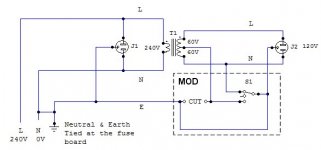
Ok well I can see why that diagram was confusing. In the center switch position "isolation mode", it also removes the protective earth. Not a good idea! This is what I've actually done:

tool.jpg

Originally the center tap on the secondary side, was tied directly to earth, giving 60V on both The L and N coming out. So I cut this connection, and added a switch, S1, in the configuration shown.

Code:
+---------------+-------------+-------------+
|               | 240V side   | 120V side   | 
|               | L    N   E  | L    N   E  |
+---------------+-------------+-------------+
|top position   | 240V 0V  0V | 120V 0V  0V | (same as USA)
|middle posiion | 240V 0V  0V | ?V   ?V  0V | (floating)
|middle posiion | 240V 0V  0V | 60V  60V 0V | (original)
+---------------+-------------+-------------+

If your unit puts a low impedance between the neutral lead and ground it will cause a short on the lower half of the winding.

I assume you mean the original 60V-0-60V configuration?

...if you break the ground loose from the center tap on the 60-0-60 winding, you should be able to connect it to the neutral (ground) on the 240V side. But that ground sitting at 60VAC will probably raise all sorts of problems.

Yes if the center tap of the secondary is connected to the neutral side of the of the 240V this will cause all sorts of problems. If center tap of the secondary is connected earth, and earth is connected to the neutral at the fuse board, then essentially you have the same circuit, no?

Leaving it to float, is an option, but isn't the 120V-0V configuration effectively the same as a US outlet now?

The PSU:
I have cracked open the wall wort and it is a little more complicated than I though. I will post back with some info soon.

Thanks for all your help.
 
Back
Top