• Please review our updated Terms and Rules here

XT 130W PSU 120V tp 240V conversion, is it possible?

Yes if the center tap of the secondary is connected to the neutral side of the of the 240V this will cause all sorts of problems. If center tap of the secondary is connected earth, and earth is connected to the neutral at the fuse board, then essentially you have the same circuit, no?

Leaving it to float, is an option, but isn't the 120V-0V configuration effectively the same as a US outlet now?

You don't want the center tap connected to anything. But yes 120-0V with the 0V connected to the ground lug--and earthed, is essentially the US system. Remember the US distribution:

120-0-120, with the 0 also earthed. The 0 side is the wider of the two prongs on a USA plug--don't get those mixed up. So the wide prong in US outlets is connected to 0, with the 3rd ground prong earthed--usually, the two are connected together in the breaker panel. The narrow prong on the US plug is connected to 120V; it doesn't matter which side of the distribution transformer winding.

US electrical code requires an independent conductor for the grounding prong, even though it may be connected to the neutral side of the line in the breaker (distribution) box. Safety is provided by a GFCI (if the fault circuit interrupter detects that the current between the two flat prongs isn't the same, the circuit is interrupted.) So, tossing a hair dryer into the bathtub will cause the (now code) GFCI to trip, regardless of what the TV murder mysteries say.

240V appliances are a different matter. An electric oven may have 4 conductors; two for the 240 heating elements, one for the 120V to run the clock and controls and a fourth for earthing the body of the oven.

On the other hand, my table saw is 240V with only a protective ground wire--but that requires a special circuit.

I do envy you fellows in the UK. Here in the US, the most powerful home vacuum cleaner available is a paltry 1440 watts. Code requires that a portable device (i.e. something that's not wired in) to draw no more than 80% of the circuit capacity. Since a lot of US homes are still wired with 15A, 120V outlets, the maximum current draw allowed is 12A.
 
Last edited:
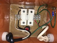
...This is what I've actually done:

View attachment 39630
Frankly I see no need for a grounded neutral option as no appliance expects that or even cares. The centre ground is the best safety option (obviously why it's used for worksite tools) and the floating output could be useful for some advanced troubleshooting.
 
It depends on what other gear you have hooked to the 120V supply. There are some bits of vintage equipment with a so-called "hot chassis", where one side of the line is connected to chassis ground. This would create a bit of a problem if the protective ground (connected to the case) were at 60VAC.

Look, it's a North American convention; best to follow it, no? You don't take a UK 240V piece of equipment and place the protective ground prong at 120VAC, do you?
 
I would guess that that 60 V is safer than placing the hot chassis at 120VAC. (Thankfully 5-valve radios in 240VAC countries have power transformers and a grounded chassis.)

The output of a portable power transformer is not house wiring and a technician can do whatever he or she feels is appropriate for troubleshooting purposes.

I've also seen the 110 VAC Center Tap Earth (CTE) standard used in industrial PLC I/O ... in the US auto industry.

...You don't take a UK 240V piece of equipment and place the protective ground prong at 120VAC, do you?

Hmm, sorry, Chuck, no one is suggesting placing the protective ground prong at 60 V. Ground is still grounded.
 
I guess I'm not following the conversation well, then. I see the low end of the 120V "neutral" and then I see the ground prong (chassis ground) hooked to the center tap (60V above neutral) US convention is neutral-ground.

I'm wondering if the setup will create issues with ground loops. Maybe I'm fussing about nothing.
 
Yes, mR_Slug's wiring diagram is slightly misleading schematically, functional but not ideal if it's really wired that way.

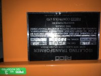
I just opened up my 1KVA NZ worksite transformer and the 110 VAC output is completely floating. I've run my US-sourced laser printer off it for the last decade.

Home wiring is going to protect against overloads and subsequent fire as a first priority and a grounded neutral is a practical standard so ground faults off Line cause a trip.

Work site power tools, and I would argue technical troubleshooting, would favor safety first so the output with a locally-grounded center tap is a good choice. Completely floating outputs have the disadvantage that you don't know you touched one side until you touch the other side, at which point it is a bit late. On a work site, cutting through a power cord could still trip the fuse/breaker and in any case with a center tapped ground, minimise the potential shock hazard.

As for ground loops, I don't see how the relative potential of the incoming AC would affect that, as long as the isolation is from a nearby transformer and does not pick up further potential capacitively, if completely floating. Of concern is the dielectric rating of the input electrics over chassis ground. You wouldn't want a floating AC input float >400V over ground because it may exceed component dielectric ratings. A center-tapped ground should not affect the functionality of any modern appliance or electronics since the AC input is fully isolated from the chassis.

IMG_0801.jpgIMG_0803.jpg pardon the rotated photo, couldn't seem to correct it
 
Last edited:
Ok, finally got some time to play with this again. The first wall-wort I took apart turned out to be a SMPS, I always thought they were all linear. The second would fit, but due to the terminals for one winding being on the top and the other on the bottom it was going to be very difficult to mount it.

I was going to measure the milliamps, but I realized my meter cant do that. It's a clamp-on thingy, intended for electricians. It is made by toolzone, so I doubt an actual electrician would buy one. As the probes were broken, and tape holding on the battery compartment fail again, I've ordered a new multimeter.

I did measure the resistance and got 7.8K which should equal 15mA. But I don't know how accurate that is, or if it's completely meaningless. I had a look around for small transformers and found this:

http://www.ebay.co.uk/itm/VIGORTRON...115810&hash=item2808e9ea92:g:rfAAAOSwcwhVNX3A

datasheet:
http://datasheet.octopart.com/VTX-120-003-606-Vigortronix-datasheet-10380009.pdf

Says its rated at 250mA, and aside from the dual primary and dual secondary, as far as I can tell it looks like it will fit the original PCB holes. I can just connect the two 6V windings, and the two 120V windings and get a 240V to 12V transformer right?
 
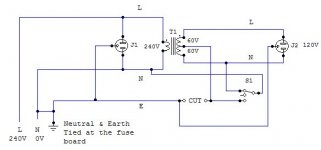
I'm looking at the drawing, if the switch is set so that the external ground
is connected to the sockets neutral, the ground on the plug will be at
60 volts.
Most equipment connect that to the physical chassis.
If one set that on a grounded surface, it would short out the 60V output of the transformer.
I would not wire it in such a configuration.
I see no big issue with grounding the center tap but the circuit as drawn
is really dangerous.
Dwight
 
Took me a while to understand what you mean. Unless I have missed something you must be referring to the first diagram I drew in post #18. Yes the diagram in post #18 is very very wrong. I have updated it in post #20.

On second thoughts, would it not make more sense to bond the neutral of the 120V to the neutral of the 240V?

Like this:
tool2.jpg

Also, I changed the typo in the thread title, by editing the post before anyone else posted. I'm sure it updated. It seems to have reverted to "tp", confusing?
 
I didn't notice the changed diagram.
The only issue is that most switches on the power supplies
only switch the hot lead.
If someone though turning it off at the switch was enough to
poke around, a screwdriver or a ring on ones hand could find
the 60V to ground.
I do like the idea of the balanced voltage for other safety reasons.
One could still manage to kill them selves with 60V but it is
safer, as you mention.
Dwight
 
On second thoughts, would it not make more sense to bond the neutral of the 120V to the neutral of the 240V?

Like this:
View attachment 39695

Umm, no. Like any other modern appliance, treat the Neutral on the incoming 240VAC as though it is "hot" because it's potential is not entirely certain. You might encounter a reverse-wired plug or overload at another point in the household circuit where that current raises the potential on N. Same reason why 240VAC appliances often switch both sides of the mains.

On your schematic you need to remove the link between the incoming N and ground since that link is not part of the transformer assembly wiring between it's 240VAC plug and the two outgoing sockets. I also note there are no fuses and you might check to see if the transformer core is tied to ground as well.

In the house we bought about 3 years ago, 20 percent of the sockets
had neutral and hot swapped.
Only 5 of them actually had the ground terminal connected.
The seller recommended the contractor he'd been using. I asked
if he'd upgraded the sockets to ground lead sockets.
"He did a good job, didn't he!"
was the response.
Dwight
 
Well I got the new transformer. I folded over the pins, and soldered the two 6V windings together and did the same for the two 120V, giving a 240-12V configuration. Then I lightly touched one of the other pins, and it broke off immediately. So I managed to solder on a lead further back where the winding connected to the pin. It turned out that my measurements were wrong, and I needed to drill 1 new hole in the PCB. So anyway I did all this, got it all soldered in, was very pleased with myself, patted my self on the back, until I realized I'm an idiot.

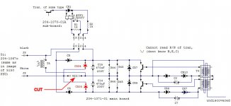
The negative side of the transformer doesn't connect directly to the negative coming in. It DID previously, but because I had removed the W23 jumper, now it just connects to the center of the two main caps. No one could have advised me of this, because my schematic was incorrect.

So my intuition on reusing the 120V transformer was right, but my schematic tracing skills need more work.

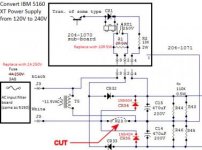
Anyway the end procedure is really quite simple, remove W23, solder in diodes at CR34 and CR35.

Updated schematic
finaldiag.jpg
So now back to the filtering board. I can order some 0.1uF X2 caps, but would .22uF X2 275V work? I seem to have some left over from anther project, and I'm itching to get this finished.

Tool transformer:
Yes it does have fuses and switches, I just didn't add them to the diagram to make it simpler.
 
Just an update. Finally got around to testing this with my actual XT. Everything is working perfectly. Thanks to everyone who helped.
 
Just an update. Finally got around to testing this with my actual XT. Everything is working perfectly. Thanks to everyone who helped.

Hello
I want to do this on my own XT PSU.

I found a couple errors on the final diagram. The diagram didn't show W23 connecting between C14 and C15.
This one has some fixes.
My board is -03 , not -01, but they are probably the same in this regard.

Could I get a run-down of what you did exactly? I find it unclear.

-Install diodes CR32 and CR33
-Remove jumper W23
-Replace T5 (115/12) with 230/12 one that fits

And by my guesses on the filter board:
- Replace X2 caps with 275V+ rated ones.
- Replace 300K resistor on filter board with 560K resistor.
- Replace 4A fuse with 2A fuse.

Thanks
JD
 
I've successfully done this conversion on a 5160 PSU of mine.

My board was the -03 version instead of your -01 version, but it's nearly identical.

Exact procedure, to clear things up:

Parts list:
- 2 x 1N5408 diodes
- 1 x 10ohm 5W resistor
- 1 x 560K 1W resistor
- 1 x 2A 250V 3AG-size fuse
- 2 x 100nF 275VAC+ "X2" film capacitors
- Torx T10H security-bit screwdriver
- ~7mm nut driver

Procedure:
- Install two 1N5408 diodes at CR32 and CR33 empty holes. (May need to drill holes slightly bigger)
- Remove jumper W23 next to J3.
- Replace R1 (2ohm 5W) on the relay board, with a 10ohm 5W.
- Replace the main fuse (4A 250V 3AG-size) on the AC-input board, with a 2A 250V 3AG-size one.
- Replace the 300K resistor on the AC input board, with a 560K 1W.
- Replace the two X2 capacitors on the AC input board, with ones rated 275VAC or higher.

Test that you still get between 9 and 12 V AC on the secondary of T5 when mains is applied.
A test load is needed to test the power supply. One 3.5" drive was not enough for me. A 5.25" drive was. Maybe two 3.5" would be.

BE CAREFUL!

IBM 5160 Power Supply 240V conversion.jpg

Also, with Paul's help, I've successfully done a late model 5150 PSU too (that differs to the one in Paul's 5150 PSU guide), and will post my findings in another thread I guess.

Cheers
JD

Note: I plan on removing my previous reply, but I cannot as I am too new to the forum.
 
Almost certainly across the X2 filter capacitor on the EMI board. It just keeps you from getting a bite from the plug pins when you disconnect from the mains.
 
Back
Top