• Please review our updated Terms and Rules here

ZX Spectrum 48K Repair. I could really use some help from the other side of the pond repairing this...

NOTE*** apparently on the issue 2 board C46 is labeled wrong on the board with positive on the right when it should be Negative on the right. I flipped the 1uf cap to be Negative on the right.
 
OK, the oscillator is dead and the 4116 ram chips are also likely faulty. If you can't test them individually, then you will need to replace them all.

TR4 and TR5 are the oscillator transistors. TR4 should be a NPN Power Transistor with a 2A capacity. It's normally TR4 that fails. It's a ZTX650 but a ZTX651 or ZTX653 are both OK. You probably won't find a convenient to92 package 2A power transistor outside of those two, so try to get the ZTX. I sometimes use a BD139 but the pinouts are different so I have to twist the legs around to make them fit.

Your 4116 chips are socketed so remove them when you fix the transistor. If they are dead, you'll just blow the transistor again. Assume they are dead from the voltages you mentioned.

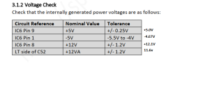
Measure the same IC6 places again. Are they the correct voltages after replacing TR4? If not, replace TR5. If you still don't have the correct voltages, then you're going to have to troubleshoot the power supply circuit end to end. Especially if you've replaced the caps.

Here's a schematic.

Once you have the correct voltages, then maybe just order a set of 4116's. They are cheap from China. Once installed, make sure you still have the correct voltages. You can also consider installing 4164's if you can't get the 4116's but keep in mind that they don't use -5v or 12v, and you'll need to disconnect those rails, bypass and tie down as necessary and then the only thing using 12v is the video circuit. But 4116's are still available and are cheap.

At this point, you should get video if your ULA is working and the z80 and ROM are working. A diagnostic rom image is a good idea too - Are you able to burn an eprom?

Regards
David
 
Hi David you must have skipped past previous posts. i removed all the 4116 Ram. verified they are all fine and socketed them.

And i do have a Tl866 programmer so i can burn an eprom
 
Yes, I agree. The oscillator appears to be doing something - but not much!

Do you have a transistor tester function on your multimeter? If so, you can test the small signal gain of each transistor (called the hfe) to see if they are working.

You can also test the transistors “on the bench” with a power supply, a couple of resistors and a multimeter.

Let me know if you require any more details and I will find a suitable webpage for you.

Dave
 
C46 (according to the schematic) looks to me as though it should be a non polarised capacitor.

Yes, if you have used equivalent transistors - then it is just possible that the pinout is different. Always check the datasheets for the components before replacing with equivalents.

It looks like the general cause for failure of the DC/DC converter is TR4, TR5 and/or C44.

Dave
 
Dave, I do have a tester. I will go over the transistors one by one today and verify orientation with the schematic.

As far as C46, the board has an obvious silkscreen for polarity and every singe board I see photos of online has a polarized capacitor in it.
 
Ok I have made some progress. But before I go into that I need some clarification on TR3. I brought it up in one of the first posts but TR3 has 4 posts. When I got this board (and who is to say it wasn't monkey'd around with) the transistor was in the 3 pin holes seen open in this photo. As you can see it has 4 possible pins and the silkscreen shows the 3 pins encircled to the left side; while my board was setup to use the 3 pins on the far right.

zx48kissue2.jpg

I went to the schematic to find orientation and its confusing me. It shows the base connecting to the left side of R24. But with the hole patten my board is using the left side of R24 connects to the emitter on TR3. Also on the schematic it shwos the Collector of TR3 connecting to the left pin of R25; but in this hole layout that would connect the base to the left pin of R25.
Why are there 4 possible holes for TR3 and why was this board using a variation not matching the schematic?
 
Last edited:
I can't see why the hole next to the VID text would be used. This is something completely different. It is the video output taken before the modulator.

The transistor should go in the three (3) holes surrounded by the white silk screen (identified as TR3) in the order as shown [e b c].

Dave
 
I would guess the 4th hole is to allow the use of an alternate part number with different pin ordering.
 
I would assume so as well. Considering that is exactly as the schematic lays it out. Like I said, this is how I received it so I just wanted to make sure . I will replace the transistor to the pins within the silkscreen and report back.
 
No, it isn't...

It is more likely this part of the circuitry and nothing to do with the Z80 (CPU) clock.

1643220724549.png
Dave
 
Ok So I replaced TR3 with a tested Transistor within the silk screen.

What I found. So per this and a couple other websites; I can replace the XTX313 with the MPS2369 (which is what I purchased and have now). I put a couple of them on wrong, including the one mod (TR6) on top of the z80. I corrected those. Replaced TR4 which was fried.

When powered up there is a high pitch buzz from the speaker now.

Here are the voltages I am getting now:
volt check.png
Per the schematic I am looking for -12V rail and it says to check on C46 or D15 and I am getting +10.3v

Going back to the polarity on C46 I still have it as negative to the right.
 

Attachments

  • volt check.png
    volt check.png
    23.6 KB · Views: 3
Excellent.

I don't think the -12V is used - so it is irrelevant.

The important thing is you have -5V for the 4116 DRAM!

As I stated in a previous post, I think the -12V point is at the junction of C46, D11 and R55 anyhow (otherwise your multimeter will be reading a DC level superimposed with an AC voltage) - which is why I think that point may be misleading.

Dave
 
Last edited:
Well we now have good voltages. Where do we go from here? Still just nothing on the screen really.
I cant read the mask rom in my tl866 (maybe its me) so I cannot verify it works.

IMG_20220126_131542.jpg
 
I am expecting to see 1 trace not 2. They appear to be of different frequencies.

What frequency is the Z80 clock pin at and what is the upper and lower voltage level of the clock signal?

It also helps to fill the screen with the signal and make sure the 0V reference is on a convenient marker line.

Dave
 
Sorry I am a bit rusty as I havent really used an Oscope in almost 15 years. I am getting about 4.3V at peak. According to my meter I am getting 3.49Mhz. That second trace comes and goes. When I have the O-scope ground connected to the speccy board I am getting different results. Could this be a grounding issue?
IMG_20220126_142419.jpg
IMG_20220126_142123.jpg


As soon as I hooked up the O-scope the buzz changed sound and I got a border on the screen with lots of color bleeding. I adjust VR2 counterclockwise and I get a clean monochrome border.
IMG_20220126_141928.jpg
IMG_20220126_141956.jpg

If I pull the power and reconnect (with O-scope gruonded to board I get different screens. Never any characters but different patterns.
IMG_20220126_142037.jpg
IMG_20220126_142017.jpg
IMG_20220126_142027.jpg

Again, I can only see these with the probe grounded to the speccy board. If I unclip the ground the screen goes to blackish nothing.
 
Like you say - this is suspicious...

The only place the video can be coming from is the ULA in the Spectrum! So something is alive... But why only when the oscilloscope ground is connected?

Is it possible that the GND side of the video connector on the Spectrum is not making contact with the Spectrum board itself?

Dave
 
Back
Top