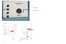
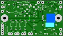
I looked at several datasheets for TO-220 regulators, all seem to specify a max of 6.35mm length for the wide portion of the pins. The holes are currently located at 6.35mm from the bottom of the package. Factoring play with the mounting hole, that should be fine. I also aligned the holes... using a 2mm pad doesn't present an issue doing so. And assuming the new pad sizes are a go for everyone, I adjusted the part positioning in the lower right corner a bit.
Last, I am assuming a double sided board. All tracks, with the exception of the regulator supply, are at the bottom and all pads are through hole.

Last, I am assuming a double sided board. All tracks, with the exception of the regulator supply, are at the bottom and all pads are through hole.
Last edited:
")