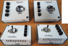
I have finished both of my units . It is always longer job when there are two of them.
(Thanks
@nullvalue for the switches & buttons)
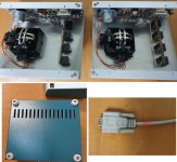
I wanted to use a tag board like the original, rather than a pcb, but the class B amplifier arrangement on the pcb did not lend itself well to a tag board, it needed more than the 10 tags.
Also I found I could help the connections to the Cherry switches by running a double sided 10mm tall section of pcb material slipped between the contacts, just etching one side of it, the other side being the earth bus, and using that to carry the 10k pullups and the 5V zener regulator, and make a stable place to connect the wires. Most of the wires I used are multi-colored Teflon insulation types, I prefer it because unlike PVC, the insulation doesn't shrink back with heat from the soldering iron.
So for my units I changed it to a class-A amp, somewhat power hungry, with a single 2N3053 transistor. It required a heat flag because the transistor heat dissipation is 1 Watt, I used the very attractive TO-5 Sylvania heat flags. And I had to design & wind the 32:8 Ohm impedance matching transformer to suit the 8 Ohm speaker.
I'm using standard style RS-232 serial cables that fit the D9 connector(whatever the correct nomenclature is), the ones I found on AU ebay were only a few dollars and the cable is 5mm outer diameter and is nice and soft/flexible.
It all worked out and the units are set up ready to go, that is after I figure out how to connect the cabling at the computer- D+7A pcb end, get my SOL-20 up and running again, restore the D+7A card, check and calibrate that before trying to run any Joystick operated software....


") Or am I missing something?
Or am I missing something?